Carrier device, work processing apparatus, control method of carrier device and storage medium storing program

a carrier device and work processing device technology, applied in the direction of program-controlled manipulators, manipulators, electrical devices, etc., can solve the problems of high humidity air entering the interior of the transfer robot, the possibility of dew condensation inside the transfer robot, and the high humidity of the inside of the transfer robo

Active Publication Date: 2022-07-05
EBARA CORP +1
View PDF12 Cites 1 Cited by
  • Summary
  • Abstract
  • Description
  • Claims
  • Application Information

AI Technical Summary

Benefits of technology

[0008]In a CMP apparatus that is one example of the work processing apparatus, in the case of cleaning a substrate after a polishing process, the substrate in a wet state is conveyed to a cleaning module by a transfer robot, with a view to suppressing fixation of slurry. In this case, the transfer robot is operated in a wet environment and is accordingly exposed to a high humidity environment. A high sealing structure, for example, a sealing mechanism / sealing member configured to prevent invasion of water and the high humidity air into the transfer robot, is employed for the transfer robot to achieve stable conveyance of the substrate in the wet environment. There is, however, still a possibility that the high humidity air enters inside of the transfer robot through a narrow gap in a part where the sealing mechanism / sealing member is provided. In the case where the sealing mechanism has any trouble or failure or in the case where the sealing property is reduced due to time degradation of the sealing member or the like, inside of the transfer robot is likely to become the state of high humidity. As a result, there is a possibility of dew condensation inside of the transfer robot. The dew condensation is likely to cause problems, such as corrosion of an internal component and detection error of a sensor. This makes it difficult to stably convey the substrate by the transfer robot, while shortening the service life of the transfer robot or increasing the frequency of inspection and maintenance required.

Problems solved by technology

There is, however, still a possibility that the high humidity air enters inside of the transfer robot through a narrow gap in a part where the sealing mechanism / sealing member is provided.
In the case where the sealing mechanism has any trouble or failure or in the case where the sealing property is reduced due to time degradation of the sealing member or the like, inside of the transfer robot is likely to become the state of high humidity.
As a result, there is a possibility of dew condensation inside of the transfer robot.
The dew condensation is likely to cause problems, such as corrosion of an internal component and detection error of a sensor.
This makes it difficult to stably convey the substrate by the transfer robot, while shortening the service life of the transfer robot or increasing the frequency of inspection and maintenance required.
Such problems are not limited to the transfer robot configured to perform conveyance to the cleaning module in the CMP apparatus but are likely to occur in any other carrier device that performs conveyance in a wet environment.

Method used


Image

  • Carrier device, work processing apparatus, control method of carrier device and storage medium storing program
  • Carrier device, work processing apparatus, control method of carrier device and storage medium storing program
  • Carrier device, work processing apparatus, control method of carrier device and storage medium storing program

Examples


first embodiment

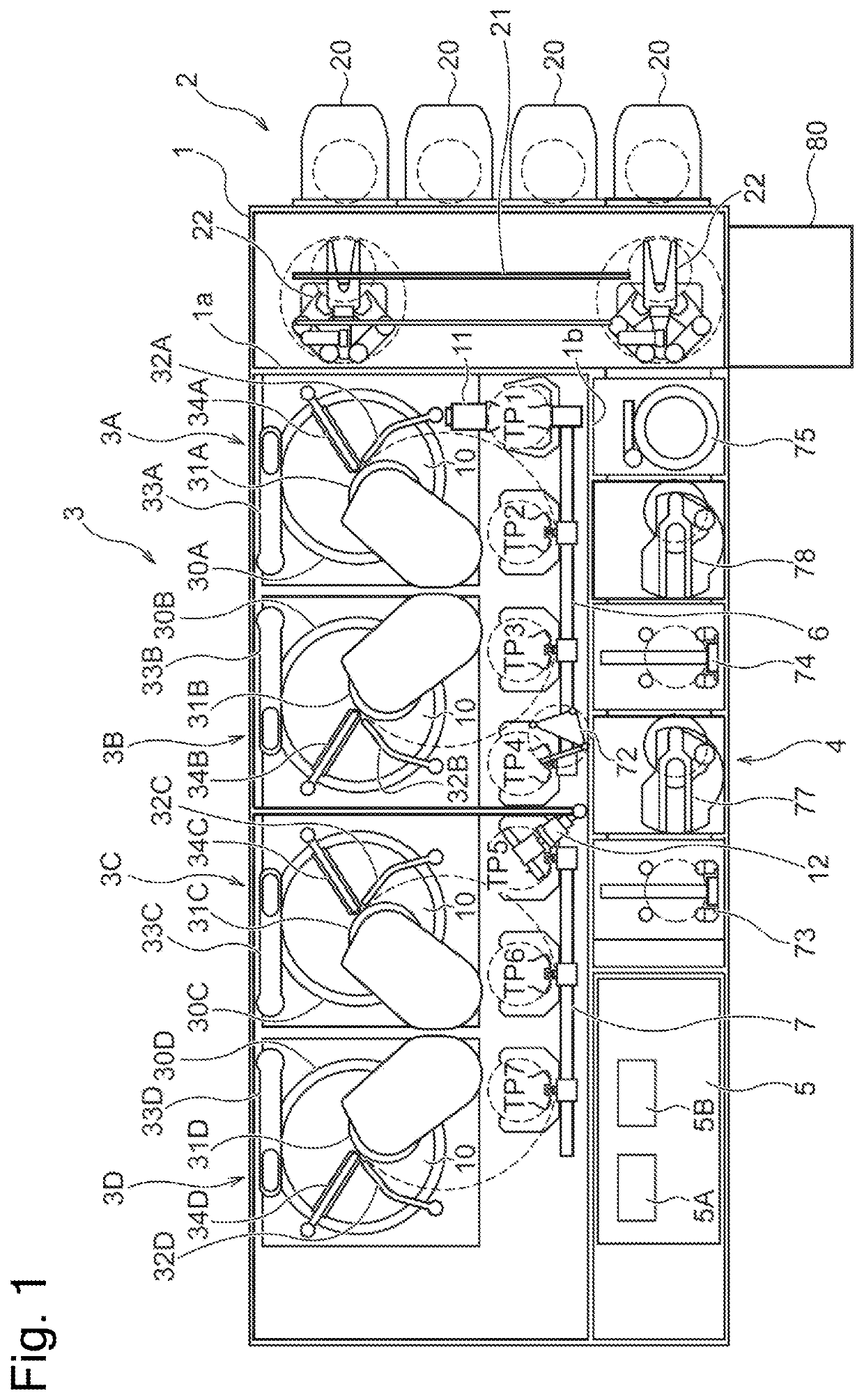
[0021]The following describes embodiments of the present disclosure with reference to drawings. FIG. 1 is a diagram illustrating a polisher device as one example of a work processing apparatus according to a first embodiment. As shown in FIG. 1, this polisher device includes a loading / unloading module 2, a polishing module 3 and a cleaning module 4. The loading / unloading module 2, the polishing module 3 and the cleaning module 4 are parted from each other by partition walls 1a and 1b inside of an approximately rectangular housing 1, as shown in FIG. 1. A controller 5 is provided inside or outside of the housing 1 to control the operations of the respective portions of the polisher device. A polishing object (object to be polished) may be any work, such as a semiconductor wafer, a printed circuit board, a liquid crystal substrate, or an MEMS. In the description below, the polishing object is simply referred to as substrate or wafer.

[0022]The loading / unloading module 2 includes front ...

third embodiment

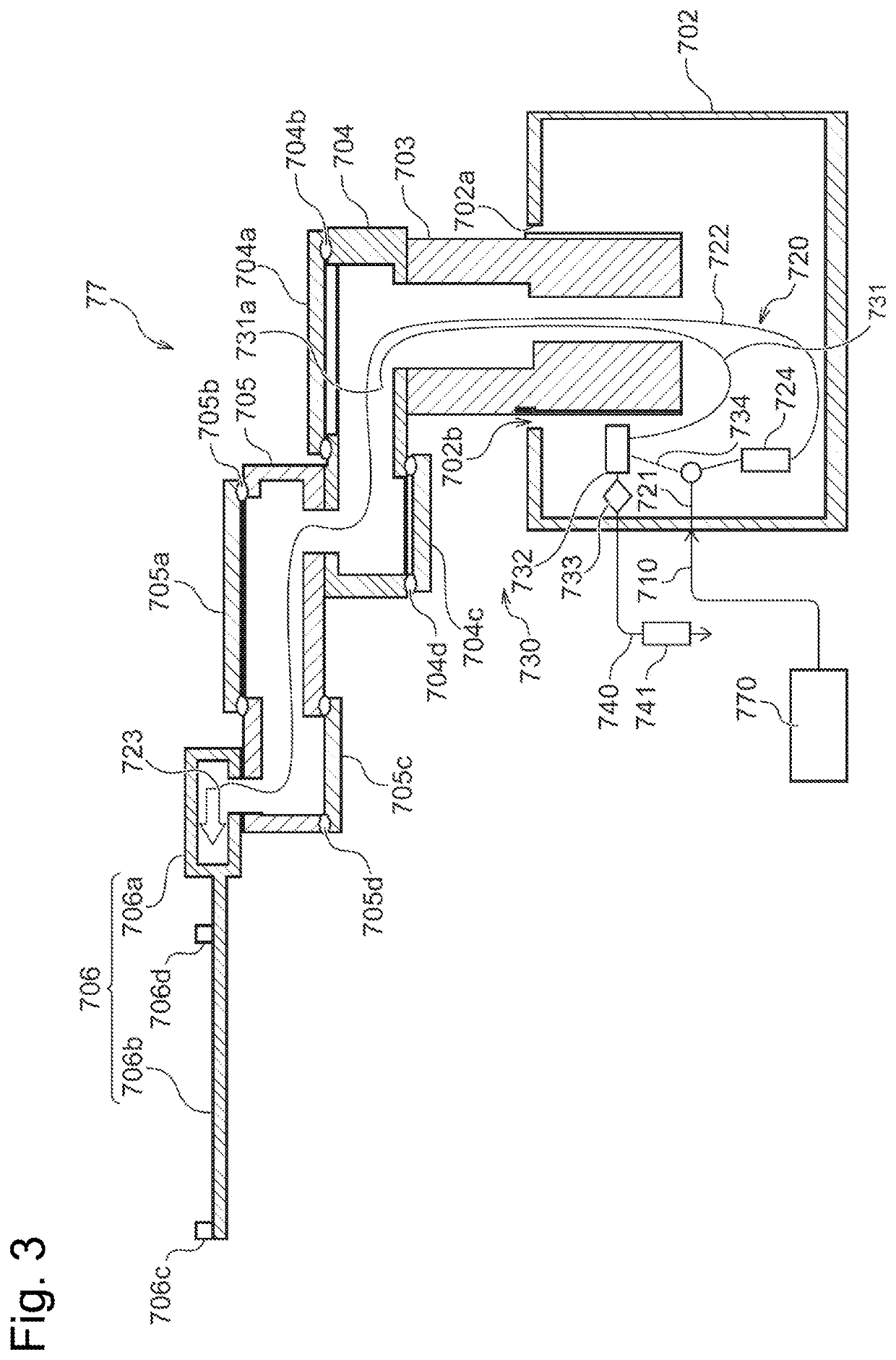
[0062]FIG. 5 is a sectional view schematically illustrating the configuration of a transfer robot according to a third embodiment. The difference of this embodiment from the embodiments described above is that a gas supply unit 720 receives the supply of the gas from a gas supply line to an existing chuck mechanism. Otherwise the configuration of this embodiment is similar to those of the above embodiments. The following describes only the differences with omitting description of the other configuration.

[0063]According to this embodiment, an end effector 706 is provided with a chuck mechanism 755, in place of the claws 706d of the first embodiment. This end effector is a so-called edge grip (chuck)-type end effector. The chuck mechanism 755 is driven by a gas that is supplied from a driving fluid supply unit 750. The chuck mechanism 755 includes a pressing member 755c, a shaft 755b connected with the pressing member 755c, and a cylinder 755a coupled with the shaft 755b. The cylinder...


PUM


Abstract

An object is to suppress dew condensation in a carrier device. There is provided a carrier device comprising a body; a rotational part provided to be rotatable relative to the body; an arm supported on the rotational part; an end effector provided in a leading end portion of the arm and configured to hold a work; a gas supply unit configured to supply a gas to an arm-side internal space provided in an arm-side base portion of the end effector and / or in the leading end portion of the arm; and an exhaust unit provided in a body-side internal space that communicates with the arm-side internal space and configured to discharge the gas in the arm-side internal space and / or in the body-side internal space.

Description

[0001]The present application claims priority from the Japanese patent application No. 2019-074397 filed on Apr. 9, 2019. The entire disclosure of the Japanese patent application No. 2019-074397 filed on Apr. 9, 2019, including specification, claims, drawings and summary is incorporated herein by reference in its entirety. The entire disclosure of Japanese Patent No. 3342803, Japanese Patent No. 3638393, Japanese Patent No. 3983481, and Japanese Patent No. 6120031 is incorporated herein by reference in its entirety.TECHNICAL FIELD[0002]The present disclosure relates to a carrier device, a work processing apparatus, a control method of the carrier device and a storage medium that stores a program therein.BACKGROUND ART[0003]In a work processing apparatus configured to process a work (or a substrate or a wafer) such as a semiconductor wafer or in a component inspection apparatus for any of various devices such as a semiconductor device, a carrier device such as a transfer robot is use...

Claims


Application Information

Patent Timeline
Patent Type & Authority Patents(United States)
IPC IPC(8): H01L21/67H01L21/677H01L21/687
CPCH01L21/67017H01L21/67173H01L21/67706H01L21/68707H01L21/67703H01L21/67092H01L21/67766H01L21/67196H01L21/67742B25J9/042B25J19/0075B25J11/0095
Inventor ETO, YOHEIKUNISAWA, JUNJIHOMBO, TERUAKIKANAZAWA, KEIJI
Owner EBARA CORP
Why Eureka
Try Eureka