
Techniques for utilizing an artificial intelligence-generated tin in generation of a final 3D design model

a technology of artificial intelligence and 3d design, applied in the direction of design optimisation/simulation, instruments, image data processing, etc., can solve the problems of laborious 3d design model creation, excessive task and counterintuitiveness, and hinder iterative refinement, so as to achieve more efficient workflow

Active Publication Date: 2022-06-28
BENTLEY SYST INC
View PDF25 Cites 0 Cited by
  • Summary
  • Abstract
  • Description
  • Claims
  • Application Information

AI Technical Summary

Benefits of technology

The patent text describes a technique for generating a 3D design model using data structures created by an AI system. The technique involves using multiple phases, or states, to define site objects and their associated spatial constraints. A conceptual phase is used to define the overall boundaries of the model, followed by preliminary and final phases to define the specific details and transition points. Changes made to the conceptual phase can be propagated up to the final phase using vertical draping, while changes made in the preliminary or final phase can be propagated down using spatial constraints. This technique helps to avoid the need for manual edits and reduces the time and effort required to create a 3D design model.

Problems solved by technology

While a TIN with a large number of triangles is desirable for AI optimization of a grading plan, this poses a problem if the TIN is to be used in a detailed 3D design model in a later stage of the planning and development of the site.
This task may be exceedingly tedious and counterintuitive, essentially preventing a user from manually “tweaking” a 3D design model that uses the TIN.
The 3D design model is laboriously created “from scratch” by a user using design modeling tools.
In addition to being highly inefficient, such workflow hinders iterative refinement.

Method used


Image

  • Techniques for utilizing an artificial intelligence-generated tin in generation of a final 3D design model
  • Techniques for utilizing an artificial intelligence-generated tin in generation of a final 3D design model
  • Techniques for utilizing an artificial intelligence-generated tin in generation of a final 3D design model

Examples


Embodiment Construction

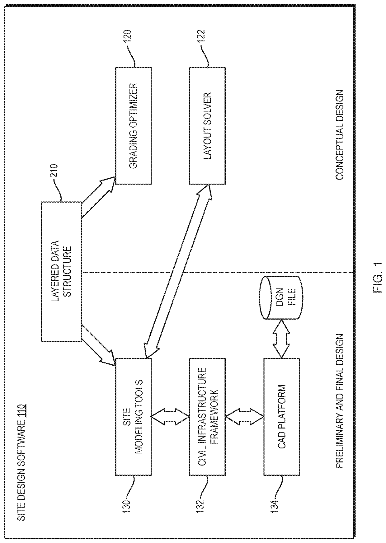
[0019]FIG. 1 is a high-level block diagram of an example software architecture in which the techniques may be implemented. The software architecture includes site design software 110 that may be executed on one or more computing devices (including processors, memory, other hardware components) local to an end-user and / or on one or more computing devices remote from the end-user (e.g., in the cloud) accessible via a network (e.g., the Internet). In one embodiment, the site design software 110 is the OpenSite™ Designer application, available from Bentley Systems, Incorporated. The site design software 110 may include software tools tailored to different types of design for a commercial, mixed use or residential land site. The types of design may include conceptual design in which initial 2D layout questions are addressed (such as “does it fit”), preliminary design in which more detail is added, including 3D aspects, and final design in which a detailed 3D design model is produced from...


PUM


Abstract

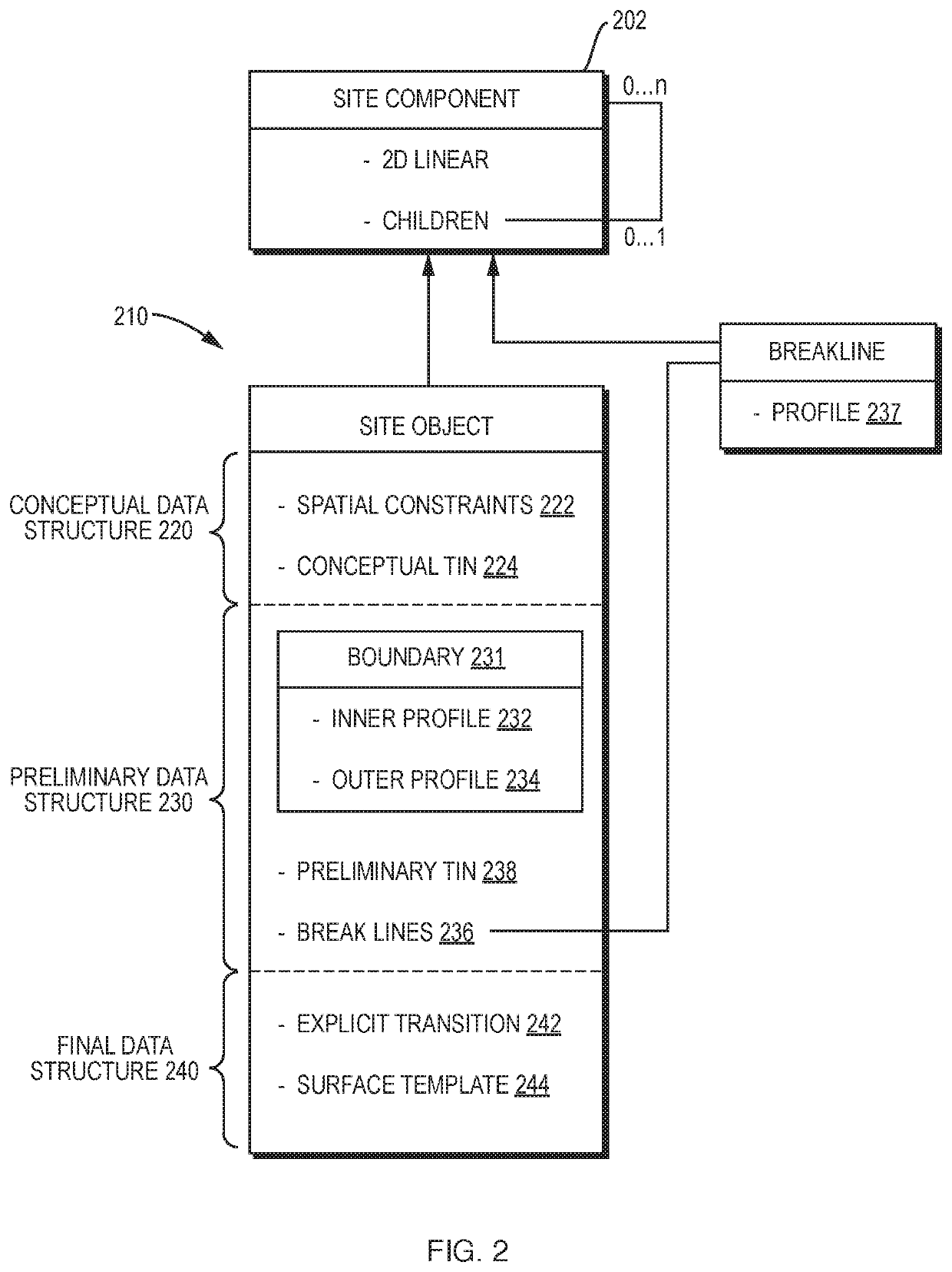
In example embodiments, techniques are provided for enabling use of an AI-generated TIN in generation of a 3D design model by defining site objects (e.g., pads) using multiple (e.g., three) phases (i.e. states). A conceptual phase may be associated with a conceptual data structure, a preliminary phase may be associated with the conceptual data structure and a preliminary data structure, a final phase may be associated with the conceptual data structure, the preliminary data structure, and a final data structure. If changes are made in the conceptual phase, for example, as a result of AI optimization, they may be propagated up to the preliminary data structure and final data structure via the vertical draping. Changes made in the preliminary phase or final phase may be propagated down to the conceptual data structure by treating boundaries and breaklines as spatial constraints.

Description

RELATED APPLICATION[0001]The present application claims the benefit of U.S. Provisional Patent Application No. 62 / 915,631 by Ron Breukelaar et al., filed on Oct. 15, 2019, titled “TECHNIQUES FOR UTILIZING AN ARTIFICIAL INTELLIGENCE-GENERATED TIN IN GENERATION OF A FINAL 3D DESIGN MODEL”, the contents of which are incorporated by reference herein in their entirety.BACKGROUNDTechnical Field[0002]The present disclosure relates generally to civil engineering, and more specifically to techniques for utilizing an artificial intelligence (AI)-generated triangulated irregular network (TIN) in generation of a 3D design model.Background Information[0003]A variety of software applications have been developed to assist in the planning and development of commercial, mixed use and residential land sites, including features such as parking lots, building footprints, sidewalks, and the like. Among other functions, such software may utilize AI to optimize a grading plan for the site. Typically, a si...

Claims


Application Information

Patent Timeline
Patent Type & Authority Patents(United States)
IPC IPC(8): G06T17/20G01C7/02G06T17/10
CPCG06T17/20G01C7/02G06T17/10G06T17/05G06F30/13G06F30/27
Inventor BREUKELAAR, RONMATHEWS, BARRYVACARASU, GABRIELSENFT, PETERDEVOE, SCOTT
Owner BENTLEY SYST INC
Learn More