Transducer structure, transducer comprising such transducer structure, and sensor comprising said transducer

a transducer and transducer technology, applied in the field of fibreoptic transducers, can solve the problems of limited geophone shape to be a long slender cylinder, the suspension mechanism of the transducer cannot be readily used for the axis the transverse axis is not easily aligned with the cylinder's axis, etc., to achieve high compressive stiffness, increase the torsional stiffness ratio ratio ratio

Active Publication Date: 2022-05-10
PIETRO FIORENTINI SPA
View PDF20 Cites 0 Cited by
  • Summary
  • Abstract
  • Description
  • Claims
  • Application Information

AI Technical Summary

Benefits of technology

[0038]In a further aspect of the present invention, the ends of the optical fibre are constrained to the supporting body so as to prevent slipping. As a result, any radial expansion of the transducer necessarily results in a strain to the fibre, the total change in length in the fibre being the strain in each loop multiplied by the length of each loop and then multiplied by the number of loops.
[0040]In a variant embodiment of the present invention, the top end of the transducer structure is an additional disc connected to the top disc of the supporting body through a mechanism arranged to have high compressive stiffness but low shear stiffness. This allows the transducer as a whole to act on compressive motions while being relatively unaffected by shearing motions. Preferably, the above mechanism takes the form of a thin rod.
[0041]In a variant of the present invention, multiple parallel thin rods can be used in place of a single rod. Such a configuration is advantageous where it is desirable to increase the torsional stiffness of the transducer while maintaining high compressive stiffness and low shear stiffness.

Problems solved by technology

However, the downhole environment is very space constrained.
However, the space constraints of the downhole environment limit the shape of a geophone to be a long slender cylinder.
As a result the suspension mechanism of the transducer can only readily be used for the axis aligned with the cylinder's axis, and not for the transverse axes.
This limits the usefulness of geophone sensors based on transducers according to the above arrangement.
However, this mechanism relies on a mechanical bearing and is therefore subject to static and kinetic friction and to wear, that limit its sensitivity and reliability.
Furthermore the effectiveness of the mechanism depends heavily on the geophone remaining substantially vertical, which is often not the case in many oil or gas well bores which may be inclined or even fully horizontal.
However, the use of a rubber mandrel has some significant disadvantages for use in downhole applications.
One of the above mentioned disadvantages is that rubber typically has a high thermal expansion coefficient.
As a result, when heating from ambient to a typical downhole temperature, the rubber expands by a sufficient amount to apply a large strain to the fibre, adversely affecting its reliability or possibly even breaking the fibre altogether.
In addition, the long-term reliability of a rubber-based mechanism at high temperatures is uncertain.
Finally, the coupling ratio of a rubber mandrel, defined as the ratio between the axial compression and the radial expansion of a rubber mandrel, is set by the geometry of the rubber cylinder and cannot be changed without changing the cylinder, and cannot be adjusted, thus limiting the versatility of the sensor.
Displacement, force or acceleration cause the disc to deform, resulting in a measurable change in length of the fibre.
Such sensors are highly robust but offer limited sensitivity due to the relatively low coupling ratio between applied displacement and change in fibre length.
As a result they are not suitable for use in high-sensitivity geophones.
However, this technique is only able to stretch a short, straight length of fibre, rather than a long length wound into multiple coils.
As a result its sensitivity is low compared to a mandrel-based design, limiting its usefulness for geophones.

Method used


Image

  • Transducer structure, transducer comprising such transducer structure, and sensor comprising said transducer
  • Transducer structure, transducer comprising such transducer structure, and sensor comprising said transducer
  • Transducer structure, transducer comprising such transducer structure, and sensor comprising said transducer

Examples


Embodiment Construction

[0054]It is hereby noticed that, for the sake of clarity, when the drawings depict a number of elements that clearly have the same function, the reference number is reported only for one of those elements, being it understood that the same reference number applies to all the other of those elements.

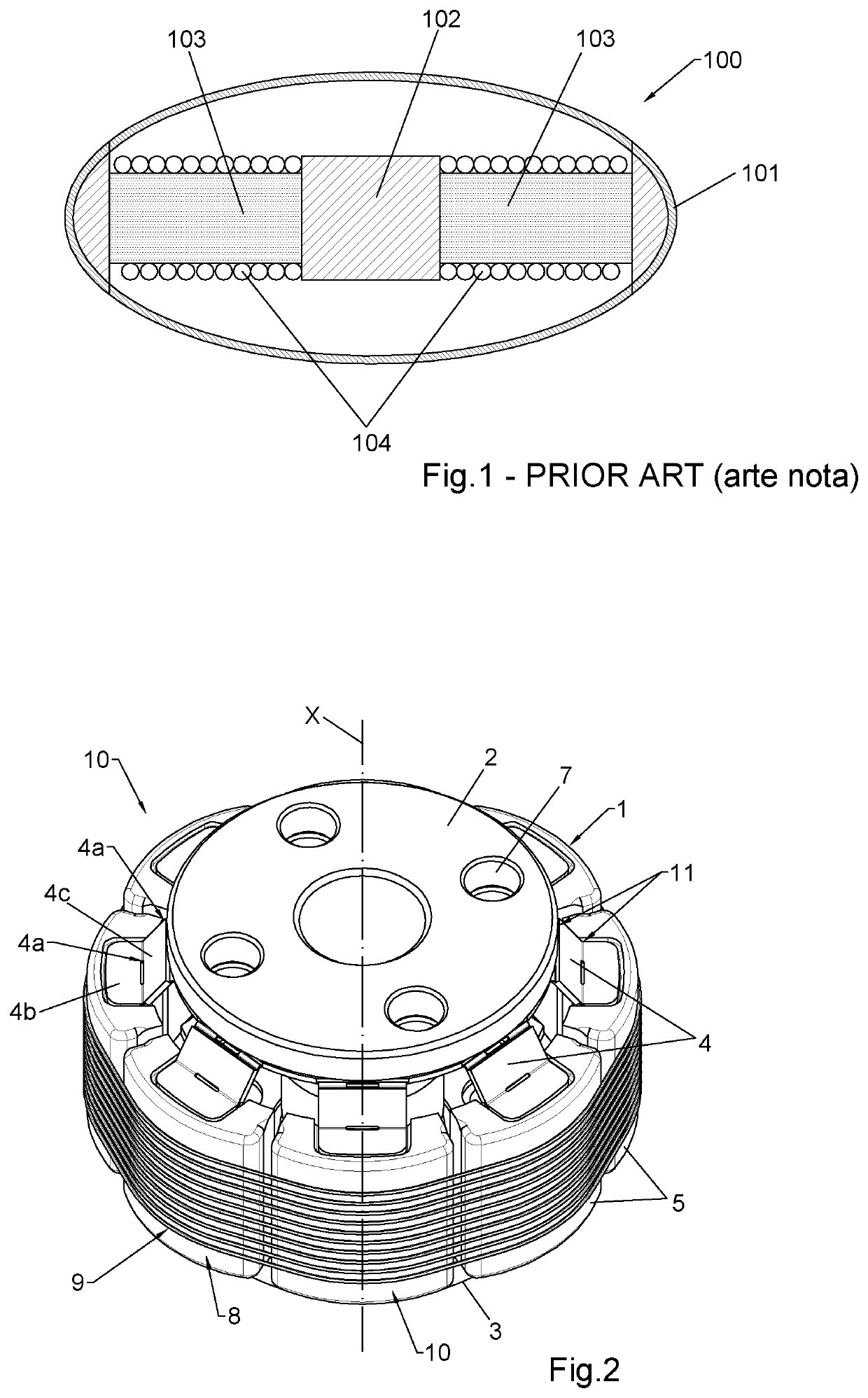
[0055]FIG. 2 shows a transducer 10 according to the present invention, comprising a transducer structure 1 adapted to convert a deformation along a reference axis X into a radial deformation orthogonal to that reference axis X.

[0056]In this preferred embodiment, the reference axis X is the axis along which it is desired to measure force or displacement.

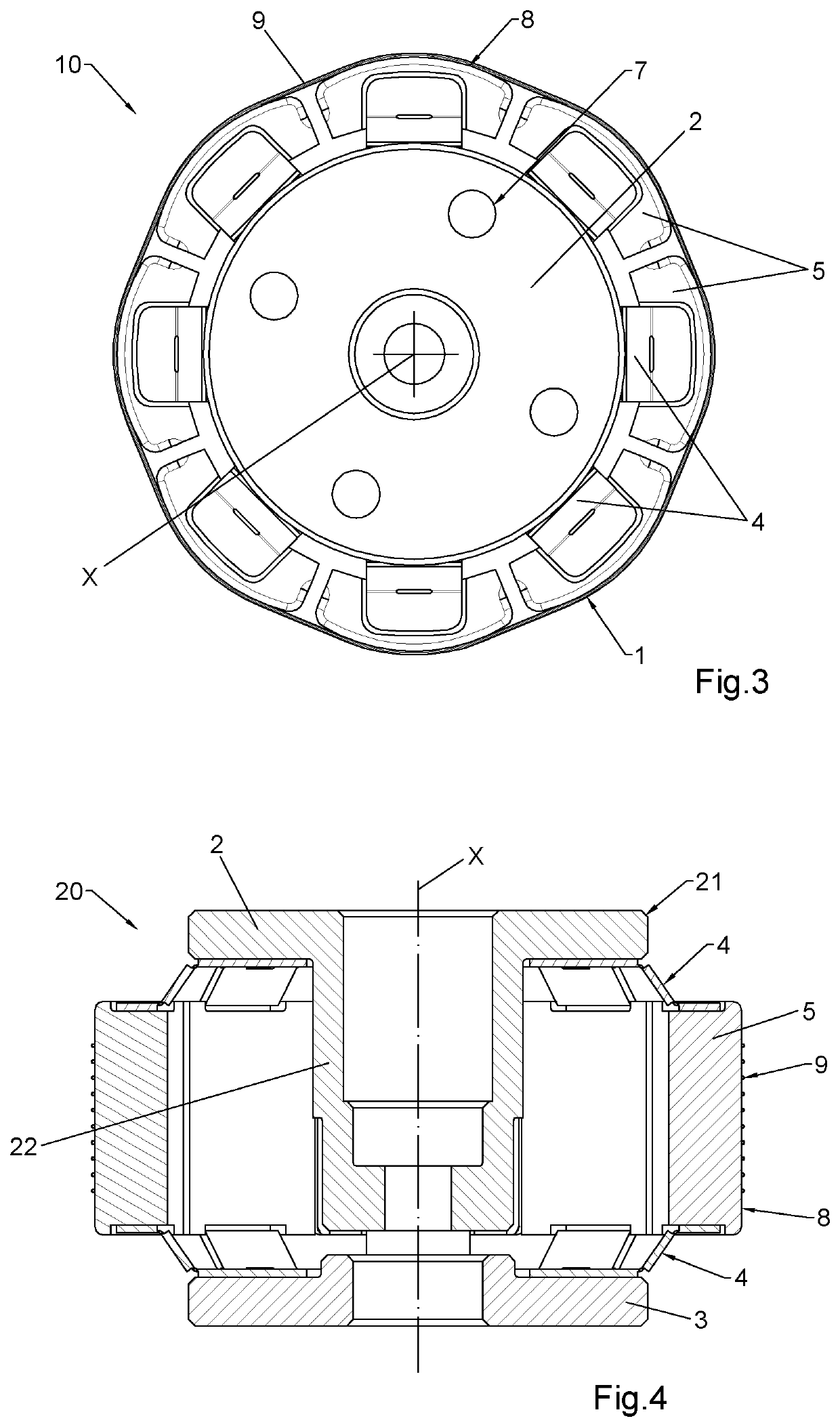
[0057]The transducer structure 1 comprises two end plates 2, 3, preferably disc-shaped, which are arranged along the reference axis X and mutually facing. Preferably, the centers of mass of both end plates 2, 3 are aligned with the reference axis X.

[0058]The transducer structure 1 also comprises a plurality of lateral bars 5, arranged aroun...


PUM

PropertyMeasurementUnit
angleaaaaaaaaaa
angleaaaaaaaaaa
pressuresaaaaaaaaaa

Abstract

A transducer structure for converting a deformation along an axis into a corresponding deformation on a plane orthogonal to the axis itself, including: two end plates facing each other and aligned along a common reference axis (X); connection members projecting radially from each end plate according to respective different directions; lateral bars connecting the end plates to one another through two connection members. The connection members are deformable within respective deformation planes to allow relative movements between the end plates and the lateral bars such as to convert an axial movement of mutual approach between the two end plates into a corresponding radial movement of the lateral bars away from the reference axis (X), and vice-versa.

Description

FIELD OF INVENTION[0001]The present invention concerns the field of the fibre-optic transducers, in particular force and displacement transducers, more particularly transducers suitable for being used in vibration sensors like, e.g., geophones.BACKGROUND OF THE INVENTION[0002]Sensors are known that transduce an external physical quantity, for example temperature, pressure or strain, into a measurable change in the optical properties of an optical fibre. The change in optical properties can then be measured by processing equipment located remotely from the location of the sensor.[0003]The above mentioned sensors offer a number of benefits over conventional sensors. In particular, they can operate at high temperatures and pressures and in the presence of strong electro-magnetic disturbances. They also allow the measurement equipment—also referred to as “interrogator”—to be located at a distance of many kilometres form the measurement location. In some cases they can also offer higher ...

Claims


Application Information

Patent Timeline
Patent Type & Authority Patents(United States)
IPC IPC(8): G01L1/18G01H9/00G01H11/08G01V1/18G01L1/24G01P15/093G01P15/12G01P15/09
CPCG01L1/183G01H9/004G01H11/08G01L1/242G01P15/09G01P15/093G01P15/122G01V1/181G01V1/182
Inventor BROCK, MARTIN EDWARDLAMB, GORDONFRY, THOMAS MURRAYKALOGEROPOULOS, XENOFONROSSER, CHRISTOPHER JAMES
Owner PIETRO FIORENTINI SPA
Why Eureka
Try Eureka