
Voice coil diaphragm

a voice coil and diaphragm technology, applied in the field of voice coil diaphragms, can solve the problems of reducing the stiffness of the expanded area, reducing and reducing the displacement of the width direction of each conductive body, so as to reduce the propagation of vibrations from each wound part to the other wound parts, and the stiffness of the entire voice coil diaphragm is kept low

Active Publication Date: 2022-04-05
HANADA AKITO
View PDF20 Cites 0 Cited by
  • Summary
  • Abstract
  • Description
  • Claims
  • Application Information

AI Technical Summary

Benefits of technology

The present invention relates to a voice coil diaphragm for an electroacoustic transducer that prevents abnormal vibrations and improves sound quality. The invention achieves this by designing the wound parts of the diaphragm in a way that they come into partial contact with each other when vibrated, reducing the stiffness of the entire diaphragm. This prevents forces in the width directions from causing abnormal vibrations. The invention also reduces the propagation of vibrations between adjacent wound parts, improving sound quality. Additionally, the invention includes a supporting body with movable linking parts that facilitate the formation of the movable parts of the diaphragm. The use of a coating film on the conductive part can further improve the adhesive force and durability of the diaphragm. Overall, the invention improves the sound quality and prevents deterioration of the sound quality of the electroacoustic transducer.

Problems solved by technology

Besides, the propagation of the vibrations causes phase-lag vibrations and divided vibrations.
This causes the vibrations of the conductive bodies 31z to be complicating, thereby having been a major cause of abnormal vibrations called flutter.
This means that the stiffness of the expanded area decreases and the width direction displacements of the conductive bodies 31z become likely to occur, and this has been a major cause of the abnormal vibrations.
In this case, however, a problem occurs that the sound quality deteriorates because substances other than the driving part (conductive bodies 31z) increase.
In this way, improving the sound quality and preventing the abnormal vibrations are in a tradeoff relationship, and thus, it has been difficult to realize an ideal loudspeaker.
Further, as the area and the amplitude of the voice coil diaphragm become larger, the range in which the width direction displacements affect on each other expands, and the abnormal vibrations become more likely to occur.
Therefore, the abnormal vibrations have been a major problem in designing loudspeakers for the mid-frequency range and the low-frequency range.

Method used


Image

  • Voice coil diaphragm
  • Voice coil diaphragm
  • Voice coil diaphragm

Examples


first embodiment

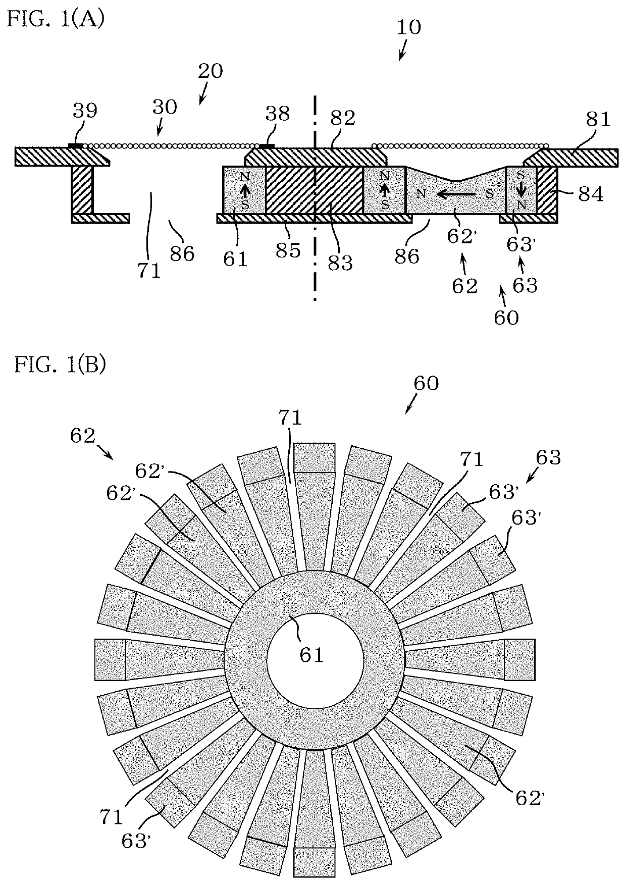
[0061]An electroacoustic transducer 10 shown in FIG. 1(A) is configured by disposing on the front side of a magnet plate 60, which will be mentioned later, a voice coil diaphragm 20 according to the present invention so as to oppose the magnet plate 60. In here, the axial directions of the voice coil diaphragm 20 are the front-back directions of the electroacoustic transducer 10. The upward direction and the downward direction of FIG. 1(A) are the front side direction and the back side direction, respectively of the electroacoustic transducer 10 (the voice coil diaphragm 20), whereas the leftward direction and the rightward direction of FIG. 1(A) are the width directions (the radial directions) of the electroacoustic transducer 10 (the voice coil diaphragm 20) (The same is also applicable in FIGS. 3, 4, 6, 8, 9, 12, 16, and 17 below). The electroacoustic transducer 10 using the voice coil diaphragm 20 according to this embodiment is suitable as a loudspeaker capable of reproducing t...

second embodiment

[0079]FIG. 4 shows an electroacoustic transducer 10A, in which the voice coil diaphragm 20A according to the present invention is disposed on the front side of a magnet plate 60A so as to oppose the magnet plate 60A.

[0080]The voice coil diaphragm 20A differs from the first embodiment, as shown in FIGS. 5 and 6, in that a conductive part 32a composing a coil body 30a is formed by three conductive bodies 31 arranged side by side and electrically connected in parallel, and in that a plurality of (in this embodiment, 20 of) string-state (line-state) supporting bodies 40a are radially arranged at an equal angle interval instead of the film-like supporting body 40. The magnet plate 60A used in combination with the voice coil diaphragm 20A differs from the magnet plate 60 in that the upper surface of each of small magnets 62a′ composing basic region magnets 62a is formed to be flat, and in that an outer peripheral region magnet 63a is formed by using one neodymium magnet into a cylindrical...


PUM


Abstract

A coil body 30 has a conductive part 32, which is made of a conductive body 31 or of a plurality of conductive bodies 31 arranged side by side in a planar shape, and an insulating part 33 for insulating the conductive part 32. The conductive body 31, or the conductive bodies 31, and the insulating part 33 are arranged in a winding state, thereby a plurality of wound parts 34 that are separated from each other and arranged side by side are formed in the coil body 30. The wound parts 34 are arranged in a manner where each wound part 34 comes into a partial contact with an adjacent one or more of the other wound parts 34 at least when vibrating and is linked by movable linking parts 41 with other ones of the wound parts 34 arranged side by side.

Description

TECHNICAL FIELD[0001]The present invention is related to a voice coil diaphragm applied to an electroacoustic transducer that converts electrical signals into sound, such as a loudspeaker, headphones, and earphones, and an electroacoustic transducer that receives sound and converts the sound into electrical signals, such as a microphone and an acoustic wave sensor.BACKGROUND ART[0002]In a cone loudspeaker that has the most common structure as a conventional loudspeaker, vibrations generated by a voice coil come out as sound after going through a voice coil bobbin and further a diaphragm. In a precise sense, in addition to the above, the vibrations go through the insulator of the voice coil, glue for joining various parts, and the like. Accordingly, the sound quality of the cone loudspeaker deteriorates through the process where the vibrations go through the various materials and propagate. Besides, the propagation of the vibrations causes phase-lag vibrations and divided vibrations....

Claims


Application Information

Patent Timeline
Patent Type & Authority Patents(United States)
IPC IPC(8): H04R7/04H04R7/16H04R9/02H04R9/06
CPCH04R7/04H04R7/16H04R9/025H04R9/06H04R9/045H04R9/047H04R7/10H04R9/00
Inventor HANADA, AKITO
Owner HANADA AKITO
Learn More