
Insect trap

a technology of insect traps and traps, applied in the field of insect traps, can solve the problems of affecting people, affecting crops and livestock, and potentially harmful insects that affect humans, and achieve the effects of reducing noise generation, maximizing insect attraction effect, and efficient use of energy

Active Publication Date: 2022-03-22
SEOUL VIOSYS CO LTD
View PDF16 Cites 0 Cited by
  • Summary
  • Abstract
  • Description
  • Claims
  • Application Information

AI Technical Summary

Benefits of technology

[0009]Exemplary embodiments provide an insect trap that is more eco-friendly, provides a more convenient manufacturing process, and secures good efficiency in attracting and suctioning insects.
[0010]Exemplary embodiments provide an insect trap that can generate a suitable air stream speed for suctioning mosquitoes while minimizing noise of a suction fan.
[0011]Exemplary embodiments provide an insect trap that is provided with a UV LED module having high efficiency in attraction of mosquitoes and emitting light having wavelengths and intensity harmless to humans.

Problems solved by technology

Insects that may be potentially harmful to humans have been recently increased in number, due to change of climate conditions such as global warming and social policies.
Harmful insects not only damage crops and livestock, but also negatively impact people by transmitting pathogenic bacteria, such as malaria, dengue, Japanese encephalitis, and the like.
However, chemical pest control methods may cause secondary contamination, and biological pest control methods or environmental pest control methods may be expensive, time consuming, and labor intensive.
In addition, conventional physical pest control methods using an insecticide or insect trap may cause user inconvenience due to complicated configurations of the insect trap or endanger users from usage of the high voltage.
However, typical UV lamps may have high power consumption, high heat generation, short lifespan, and environmental pollution due to toxic gas supplied to the lamps.
However, conventional insect traps that collect insects using the suction fan after attracting the insects by utilizing a typical UV LED have problems, such as: noise generated by a suction fan due to fouling of dead insects, such as mosquitoes, on the suction fan; escape of mosquitoes from the insect trap; insufficient suctioning of mosquitoes into the insect trap due to difficulty in controlling the speed of the suction fan; and low suction efficiency or high power consumption due to difficulty in controlling an air stream generated by the insect trap.

Method used


Image

  • Insect trap
  • Insect trap
  • Insect trap

Examples


embodiment 1

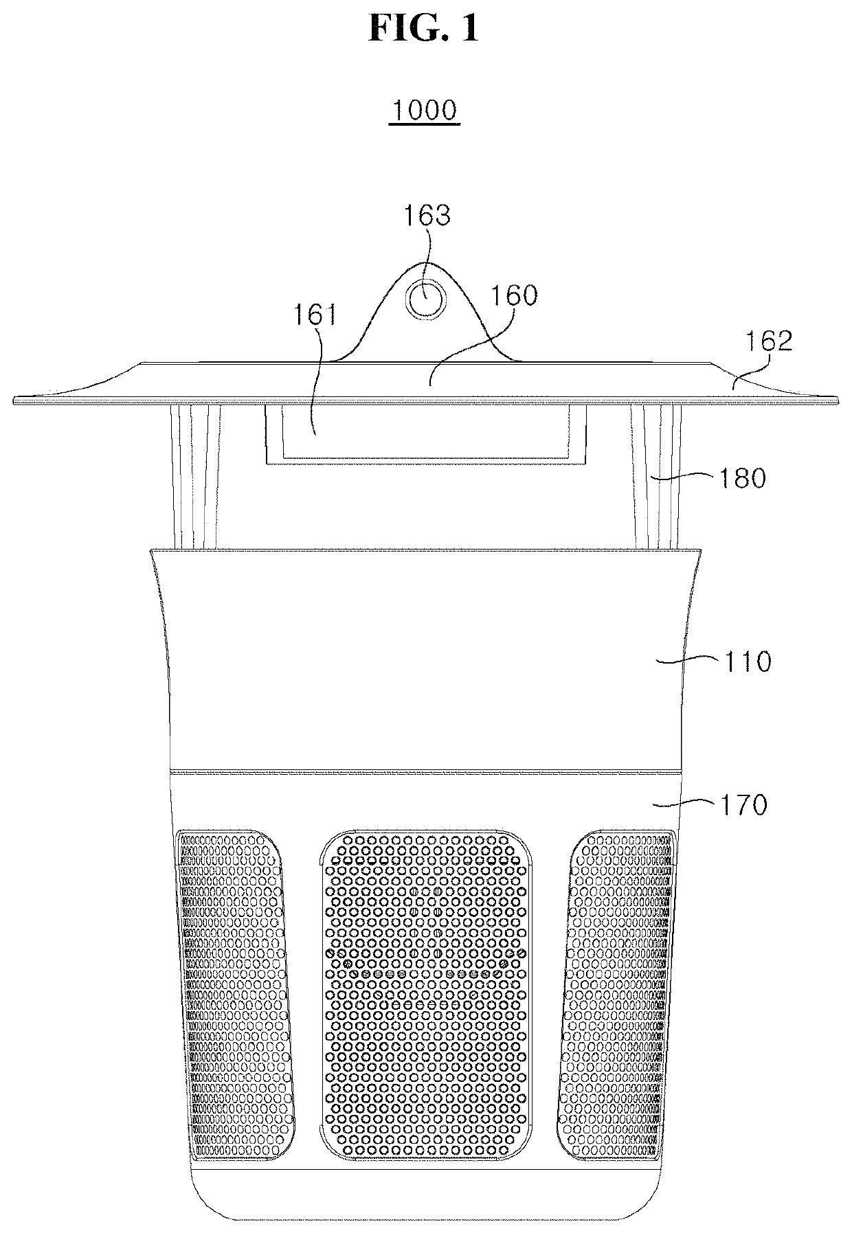
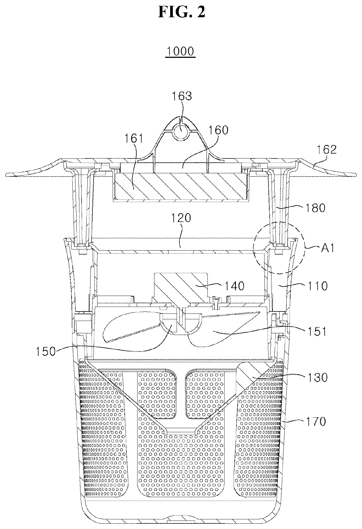
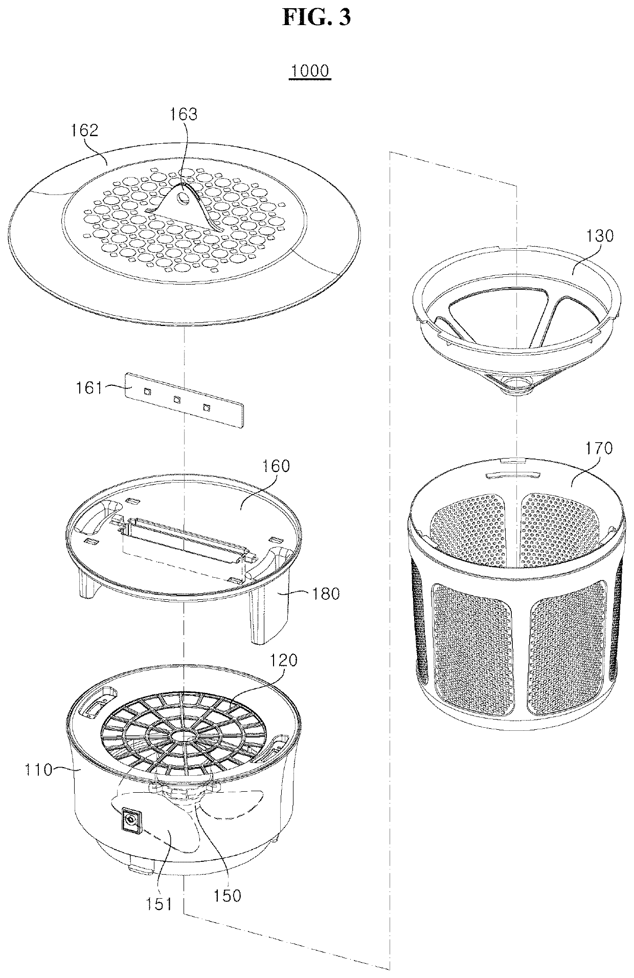
[0058]FIG. 1 is a side view of an insect trap according to a first embodiment of the present disclosure, FIG. 2 is a side-sectional view of the insect trap according to the first embodiment of the present disclosure, and FIG. 3 is an exploded perspective view of the insect trap according to the first embodiment of the present disclosure.

[0059]Referring to FIG. 1 to FIG. 3, each component of an insect trap 1000 according to a first embodiment will be described in detail.

[0060]In order to collect insects after attracting the insects using UV light, the insect trap 1000 according to an exemplary embodiment includes a main body 110, an insect filter 120 detachably coupled to an upper side of the main body 110 and selectively allowing insects to pass therethrough, an air collector 130 disposed at a lower side of the main body 110, a motor 140 disposed between the air collector 130 and the insect filter 120, a suction fan 150 disposed between the motor 140 and the air collector 130 and ro...

embodiment 2

[0130]An insect trap 2000 (not shown) according to a second embodiment of the present disclosure has the same configuration as the insect trap according to the first embodiment except for a photocatalyst filter. Hereinafter, the photocatalyst filter will be described in detail.

[0131]The photocatalyst filter can perform a deodorization function using UV light emitted from the UV LED module 161 as a catalyst and can generate carbon dioxide. The photocatalyst filter may be disposed at any location in the insect trap 2000 so long as the photocatalyst filter can receive UV light emitted from the UV LED module 161. For example, the photocatalyst filter may be disposed on the main body 110, the insect filter 120, the air collector 130, the UV LED installation unit 160, the UV LED installation unit cap 162, and the mesh member 171, preferably on a lower surface of the UV LED installation unit 160 and / or a lower surface of the UV LED installation unit cap 162.

[0132]Preferably, the photocatal...

embodiment 3

[0139]Referring to FIG. 23, an insect trap 3000 according to a third exemplary embodiment may further include an insecticidal UV LED installation unit 190, on which an insecticidal UV LED module 191 is mounted. The insecticidal UV LED module 191 may emit light having a wavelength of 200 nm to 300 nm.

[0140]The insect trap 3000 according to the third exemplary embodiment is similar to the insect trap according to the first exemplary embodiment except that the insect trap 3000 further includes the insecticidal UV LED installation unit 190, on which the insecticidal UV LED module 191 is mounted. Thus, the following description will focus on the insecticidal UV LED installation unit 190, on which the insecticidal UV LED module 191 is mounted.

[0141]Although not limited to a particular location, the insecticidal UV LED installation unit 190 is preferably mounted on the insect collector 170 in which collected insects stay for the longest period of time.

[0142]That is, the insect trap 3000 ca...


PUM


Abstract

An insect trap is adapted to attract and collect insects with UV light. The insect trap includes: a main body; an insect filter disposed on the main body and allowing insects to pass therethrough; a motor disposed below the insect filter; a suction fan disposed under the motor and rotated by the motor; a plate-shaped UV LED installation unit disposed above the insect filter and provided with a UV LED module; a buttress supporting the UV LED installation unit above the main body while separating the UV LED installation unit above the main body so as to allow insects to be suctioned into a space between the main body and the UV LED installation unit; and an insect collector disposed under the main body and collecting insects.

Description

CROSS REFERENCE TO RELATED APPLICATION[0001]This application is a Bypass Continuation of International Patent Application No. PCT / KR2016 / 010104, filed on Sep. 8, 2016, and a Bypass Continuation of International Patent Application No. PCT / KR2016 / 010109, filed on Sep. 8, 2016, and claims priority to and the benefit of Korean Patent Application No. 10-2016-0030419, filed on Mar. 14, 2016, Korean Patent Application No. 10-2016-0093593, filed on Jul. 22, 2016, and Korean Patent Application No. 10-2016-0051693, filed on Apr. 27, 2016, all of which are incorporated by reference for all purposes as if fully set forth herein.BACKGROUNDField[0002]Exemplary embodiments / implementations of the invention relate generally to an insect trap, and more specifically, to an insect trap that attracts insects by decoy light and collects insects by suctioning the insects using an air stream generated by a suction fan.Discussion of the Background[0003]Insects that may be potentially harmful to humans have ...

Claims


Application Information

Patent Timeline
Patent Type & Authority Patents(United States)
IPC IPC(8): A01M1/08A01M1/06A01M1/10
CPCA01M1/08A01M1/06A01M1/10A01M2200/01F21V33/008F21W2131/109
Inventor EOM, HOON SIK
Owner SEOUL VIOSYS CO LTD
Learn More