
Materials that resist fouling and methods for identifying same

a technology of resisting fouling and materials, applied in the direction of biocides, coatings, lighting and heating apparatus, etc., can solve problems such as inability to vary, and achieve the effects of reducing or eliminating initial deposition of foulant, reducing fouling, and eliminating fouling

Active Publication Date: 2022-03-08
MASSACHUSETTS INST OF TECH
View PDF8 Cites 1 Cited by
  • Summary
  • Abstract
  • Description
  • Claims
  • Application Information

AI Technical Summary

Benefits of technology

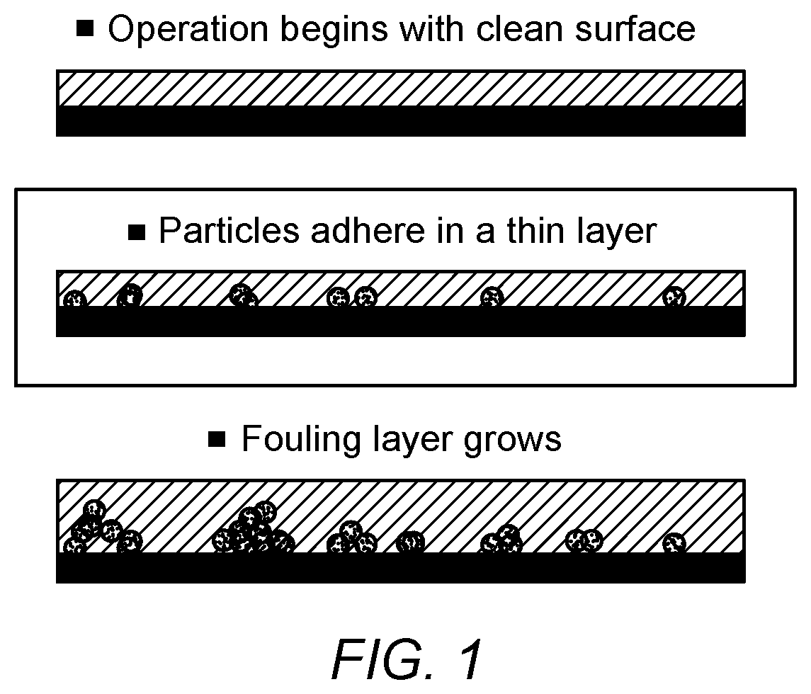
[0005]Initial fouling or initial deposition of a foulant on a surface can be caused by van der Waals forces, often the main force determining the adhesion of foulants in energy systems. Therefore, preventing such forces should reduce or eliminate any initial deposition of the foulant caused by van der Waals forces, which, in turn, would result in reduced fouling or in the elimination of fouling. The theory of van der Waals forces shows that by obtaining or engineering a close match between the dielectric spectra of either the surface being fouled or of the foulant with that of the fluid would lead to the significant reduction or elimination of van der Waals forces. Of course, for a given system, the potential foulant and the fluid are essentially fixed or determined by the system and may not be capable of variation. In other words, the compositions of the foulant and the fluid may not be changed simply to prevent fouling without sacrificing the main objective of the system in the first place. Therefore, by selecting a material of construction for the surface exposed to potential fouling, either as a coating or as the material itself, with a dielectric spectrum that matches or approximates that of the fluid to which it is exposed should reduce or eliminate van der Waal forces such that deposition of the foulant is prevented.

Problems solved by technology

Of course, for a given system, the potential foulant and the fluid are essentially fixed or determined by the system and may not be capable of variation.

Method used


Image

  • Materials that resist fouling and methods for identifying same
  • Materials that resist fouling and methods for identifying same
  • Materials that resist fouling and methods for identifying same

Examples


Embodiment Construction

[0017]Various embodiments of the invention are described below in conjunction with the Figures. However, this description should not be viewed as limiting the scope of the present invention or as setting forth the only embodiments of the invention. Rather, it should be considered as exemplary of various embodiments of the invention since invention encompasses other embodiments not specifically recited in this description such as alternatives, modifications, and equivalents within the spirit and scope of the invention and as defined by the claims. Accordingly, it should be appreciated that references to “the invention” or “the present invention” should not be construed as meaning that the invention is directed to only one embodiment or that every embodiment must contain a given feature described in connection with another embodiment or described in connection with the use of such phrases.

[0018]In general, the present invention is directed to materials that in use resist fouling on th...


PUM

PropertyMeasurementUnit
index of refractionaaaaaaaaaa
adhesionaaaaaaaaaa
optical spectrumaaaaaaaaaa

Abstract

In general, the present invention is directed to materials that when in use resist fouling on their surfaces. Such materials may be used in the construction of various process equipment having surfaces exposed to a given fluid that contains a foulant or chemical substance that may deposit on, or adhere to, the surface and thereafter continue to grow on the surface resulting in deteriorated performance of the equipment and process. The materials are specifically selected using a method that takes into account the dielectric spectra of the fluid to which the surface is exposed and the surface itself. It has been unexpectedly found that if the dielectric spectra of the surface and the fluid are matched to within relative agreement, there should be no adhesion of the foulant on the surface. In some embodiments, the dielectric spectra to be matched include the intrinsic indexes of refraction.

Description

CROSS-REFERENCE TO RELATED APPLICATIONS[0001]This application claims the benefit of provisional Application No. 62 / 567,707, filed Oct. 3, 2017. The entirety of the foregoing application is incorporated by reference herein.BACKGROUND OF THE INVENTIONField of the Invention[0002]The present invention is directed to methods for the reduction or elimination of fouling on material or component surfaces. More specifically, the present invention is directed to methods for the identification of materials of construction for such surfaces, either as coatings or as the materials themselves, having a dielectric spectrum that matches or is similar to that of the fluid to which the surface is exposed.Description of Related Art[0003]Fouling of a surface, or the undesired deposition of materials onto a given surface, is a problem that affects fields ranging from energy to transportation to medicine. Energy production and distribution systems are particularly susceptible to the detriments associated...

Claims


Application Information

Patent Timeline
Patent Type & Authority Patents(United States)
IPC IPC(8): C09D5/00C09D1/00C09D5/16
CPCC09D5/00C09D1/00C09D5/16F24T10/00
Inventor SHORT, MICHAEL P.CARLSON, MAX B.
Owner MASSACHUSETTS INST OF TECH
Learn More