
Motor

a technology of coils and motors, applied in the direction of windings, dynamo-electric machines, electrical apparatus, etc., can solve the problems of uneven heat distribution in the coils, heat is a factor of lowering etc., and achieve the effect of increasing the heat radiation effect of the coils, and improving the efficiency of the motor

Active Publication Date: 2021-12-07
PANASONIC INTELLECTUAL PROPERTY MANAGEMENT CO LTD
View PDF19 Cites 0 Cited by
  • Summary
  • Abstract
  • Description
  • Claims
  • Application Information

AI Technical Summary

Benefits of technology

The patent text describes a technique to increase heat radiation from motor coils to achieve a more efficient motor. By designing the ends of the coils to have a larger cross-sectional area than the center, heat can easily radiate from the center to the ends and the coils can average thermal efficiency. This results in further increased heat radiation effects from the coils and achieves a highly efficient motor.

Problems solved by technology

On the other hand, heat is a factor of lowering efficiency of a motor.
Heat distribution in the coils is therefore not uniform.

Method used


Image

  • Motor
  • Motor
  • Motor

Examples


Embodiment Construction

7]An exemplary embodiment will be described herein in detail with reference to the accompanying drawings. The preferable exemplary embodiment described below is a substantially mere example, and does not intend to limit the present invention, applications, and purposes.

EXEMPLARY EMBODIMENT

(Motor Structure)

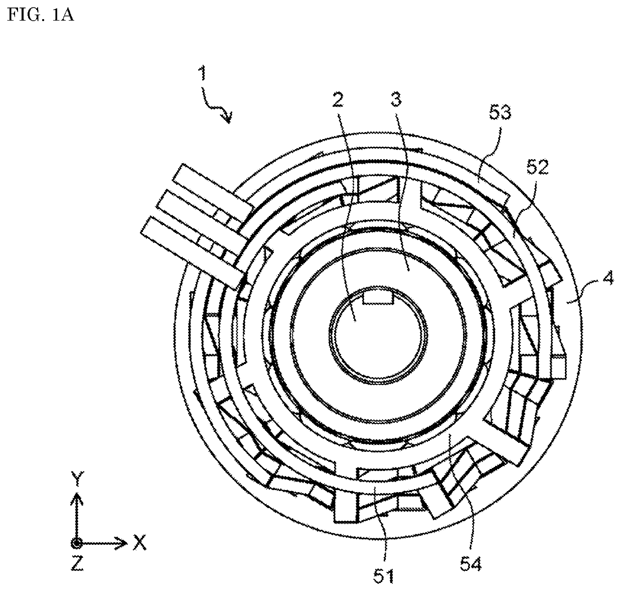
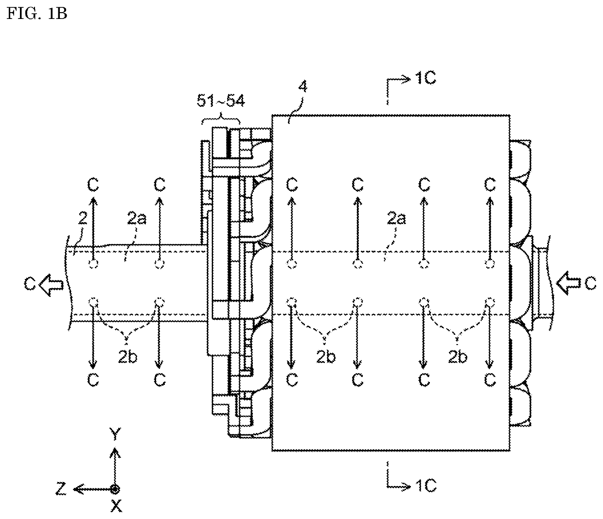
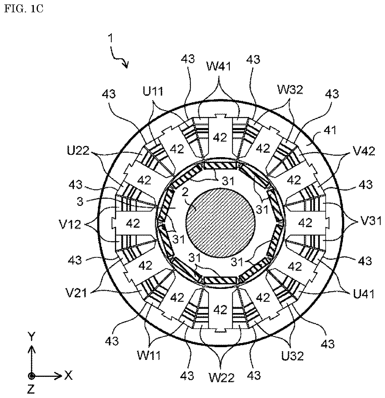
[0028]FIG. 1A is a top view illustrating motor 1 according to an exemplary embodiment. FIG. 1B is a side view illustrating motor 1 according to the exemplary embodiment. FIG. 1C is a cross-sectional view taken along line 1C-1C in FIG. 1B. However, the views do not illustrate a cover case, for example. In FIG. 1C, only a main part is illustrated as a hatched cross section. Inside of the cover case (not illustrated), motor 1 includes shaft 2, rotor 3, stator 4, coils U11 to U41, V12 to V42, and W11 to W41, and bus bars 51 to 54.

[0029]In here, a longer direction (a direction vertical to a paper plane of FIG. 1A) of shaft 2 is referred to as a Z-axis direction. Directions orthogonal to...


PUM


Abstract

A motor includes a stator including a stator core and teeth respectively protruding from the stator core in predetermined directions of protrusion, and coils respectively wound onto the teeth n (n is an integer of 3 or greater) turns including first to n-th turns. A k-th (k is an integer, 1<k<n) turn of each of the coils lies at a center of a range wound with each of the coils onto the teeth in a corresponding one of the directions of protrusion of the teeth from the stator core. Each of the first turn and the n-th turn when each of the coils is cut in a corresponding one of the directions of protrusion of the teeth is greater in cross-sectional area than the k-th turn.

Description

TECHNICAL FIELD[0001]The technique disclosed herein relates to a structure of coils in a motor.BACKGROUND ART[0002]Industry motors and on-vehicle motors have been highly demanded in recent years. In particular, a low cost but highly efficient motor has been demanded.[0003]As a method for improving efficiency of a motor, increasing a space factor of coils respectively disposed within slots of a stator has been known. Increasing a space factor of coils can suppress a loss due to a current flowing into the coils when a motor is driven.[0004]As a method for increasing a space factor of coils, such a configuration has been proposed that molded coils made of a copper material are respectively disposed within slots (e.g., see PTL 1).[0005]When coils are produced through molding or forming, for example, the coils have been each made uniform in cross-sectional area to achieve uniform resistance. On the other hand, heat is a factor of lowering efficiency of a motor. When Joule heat is generat...

Claims


Application Information

Patent Timeline
Patent Type & Authority Patents(United States)
IPC IPC(8): H02K3/12H02K3/28H02K3/52
CPCH02K3/12H02K3/28H02K3/525H02K3/18H02K9/00
Inventor YOSHIKAWA, YUICHINUKADA, KEIICHIROYAMAUCHI, HIROKAZUHISHIDA, MITSUOKIKATO, YASUSHI
Owner PANASONIC INTELLECTUAL PROPERTY MANAGEMENT CO LTD
Learn More