
Method for encoding and decoding data by varying the distinctive characteristics of an optical radiation, encoding device and decoding system

a data and optical radiation technology, applied in the field of data coding and decoding systems, can solve problems such as security, ciphering by transmitting on a wireless channel has always been subject to fraudulent receipt by non-authorised users, and full receipt of ciphered messages can be subject to brute force attacks

Active Publication Date: 2021-10-12
SLUX SAGL
View PDF4 Cites 0 Cited by
  • Summary
  • Abstract
  • Description
  • Claims
  • Application Information

AI Technical Summary

Benefits of technology

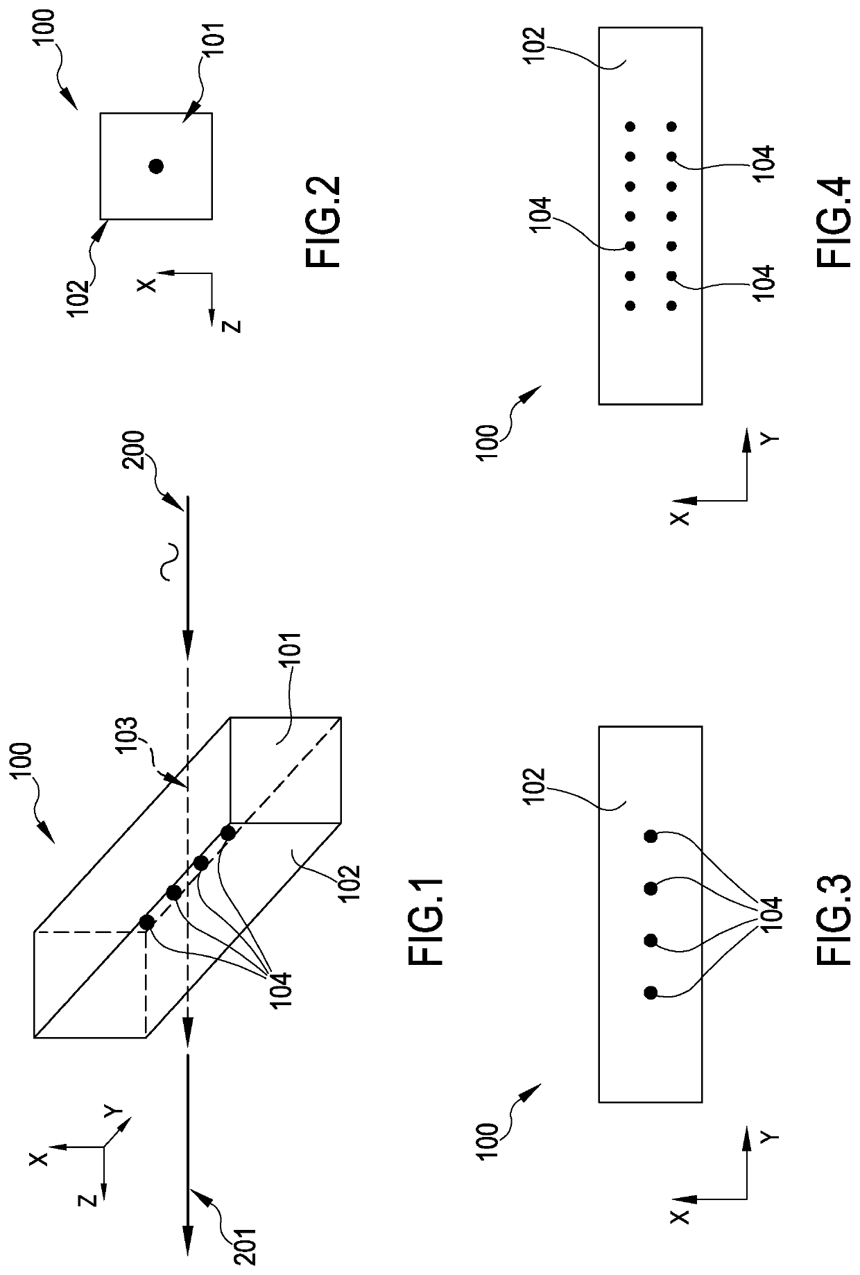
[0021]Advantageously, thus by so doing, the area that is heated locally to vary the its polarisation characteristics for the incident optical radiation, and specifically its polarisation angle, is protected by a determined thickness of the element on the three dimensions taken by the latter, and it is thus less subjected to the risk of alteration due to mechanical or chemical actions typical of the external environment, even in aggressive atmosphere.
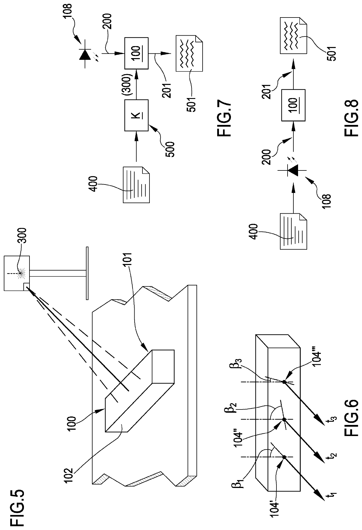
[0099]This is particularly advantageous if only a ciphering key is stored in said encoding element, given that the unencrypted message, or message previously pre-encrypted according to a second key, is directly transmitted by the radiation source.

Problems solved by technology

For quite some time now, with the increase of the amount of data exchanged electronically between two or more users there has arisen the problem related to the security thereof, irrespective of the method of transmission.
In particular, the applicant observed that ciphering by transmitting on a wireless channel has always been subject to fraudulent receipt by non-authorised users.
The full receipt of a ciphered message can be subject of brute force attacks aimed at deciphering the content—the unencrypted text that is—without any access to the key whatsoever and without guides therefor.
Such storage devices reveal a limit lying in their physical dimension and they are subject to possible malfunctioning if subjected to unfavourable environments such as for example but not limitedly high environmental temperatures, humidity or—even worse—submersion, ionising radiations or interferences or electromagnetic pulses.
Should the environmental conditions be unfavourable, the ciphered message is corrupted, and the end user can no longer recover the correct unencrypted text even though the user has the correct decoding key.
Furthermore, with some types of ciphering algorithm, the correct text could be wholly jeopardised even though for example only part of said memory has been corrupted.

Method used


Image

  • Method for encoding and decoding data by varying the distinctive characteristics of an optical radiation, encoding device and decoding system
  • Method for encoding and decoding data by varying the distinctive characteristics of an optical radiation, encoding device and decoding system
  • Method for encoding and decoding data by varying the distinctive characteristics of an optical radiation, encoding device and decoding system

Examples


Embodiment Construction

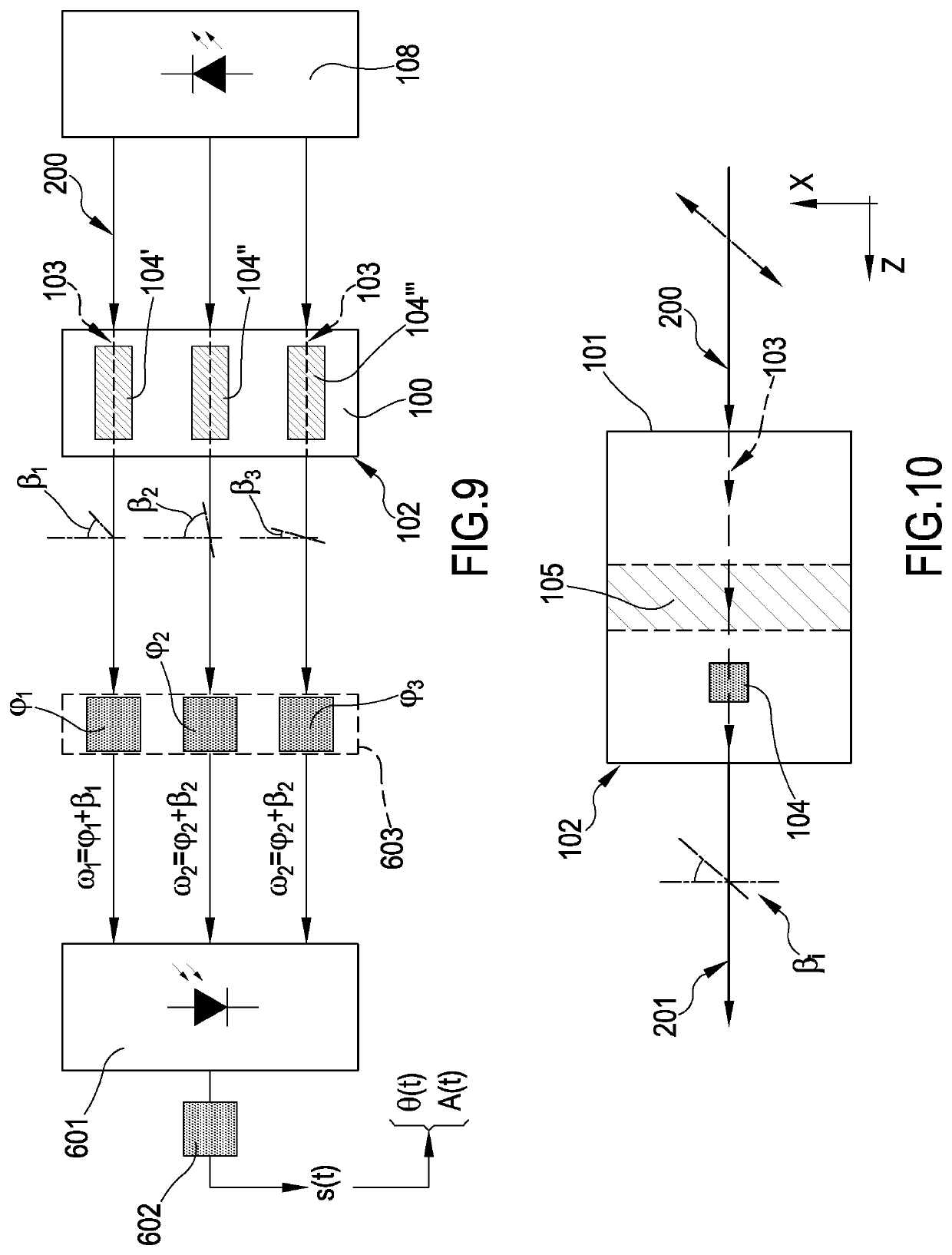
[0123]First and foremost, the present invention regards an encoding element 100 at least selectively transparent to a luminous, infrared or ultraviolet radiation.

[0124]The encoding element 100 comprises at least one first surface 101 which represents a first input or incidence surface for a radiation 200 and a second surface 102 which represents a second output surface for said radiation 200, which passes—in the volume defined by the encoding element 100—through a preferential optical path 103 defined between the first and second surface 102. Though the preferential optical path 103 is preferably straight, this configuration shall not be deemed to be limiting. As a matter of fact, for particular configurations of the encoding element 100, the first incidence surface and the second output surface of said radiation 200 can coincide. This is particularly the case when obtaining full reflections inside the element. Likewise, though the attached figures show a parallelepiped-shaped encod...


PUM

PropertyMeasurementUnit
polarisation angle β3aaaaaaaaaa

Abstract

Encoding element (100) at least selectively transparent to an infrared or ultraviolet light radiation, incident thereon on a first incidence surface (101), wherein—in the volume defined by said encoding element (100)—a plurality of areas (104) is provided, previously selected and arranged according to a predefined pattern wherein at least one polarisation characteristic of the optical radiation (200) that is incident thereon is varied, wherein the variation of said polarisation characteristic of said incident radiation is varied according to a localised alteration pattern biunivocally associated to a predefined ciphering key, and wherein said plurality of areas is arranged between said first incidence surface (101) on which said infrared or ultraviolet light radiation is incident in use, and a second output surface (102) of said infrared or ultraviolet light optical radiation.

Description

FIELD OF THE INVENTION[0001]The present invention regards data coding and decoding systems. More in particular, the present invention regards a data coding and decoding method by varying the distinctive characteristics of an optical radiation, and it further regards an encoding device and a data decoding system by varying the distinctive characteristics of an optical radiation.STATE OF THE ART[0002]For quite some time now, with the increase of the amount of data exchanged electronically between two or more users there has arisen the problem related to the security thereof, irrespective of the method of transmission. For several decades, there have been known data coding and decoding methods aimed at ciphering a data of origin which represents the unencrypted text turning it into a ciphered message, with the aim of making it impossible to correctly decipher it unless by means of a key, which should be theoretically exclusively in the possession of the right end user, authorised to pe...

Claims


Application Information

Patent Timeline
Patent Type & Authority Patents(United States)
IPC IPC(8): H04L9/08H04K1/04H04K1/08H04L9/06
CPCH04L9/0858H04K1/04H04K1/08H04L9/0618H04K1/00
Inventor PASQUALI, ALESSANDRO
Owner SLUX SAGL
Learn More