
Wrapped hose heater assembly with hot pocket configuration

a technology of hose heater and hot pocket, which is applied in the direction of ohmic resistance heating, electric heating, electrical equipment, etc., can solve the problems of increasing manufacturing costs, complex manufacturing, and inability to meet the needs of universal heating hose assemblies suitable for most any application, so as to improve installation and enhance heating efficiency

Active Publication Date: 2021-10-12
PARKER INTANGIBLES LLC
View PDF9 Cites 0 Cited by
  • Summary
  • Abstract
  • Description
  • Claims
  • Application Information

AI Technical Summary

Benefits of technology

This patent is about a heating assembly that can be used with different types of hoses and power sources. It includes a heater strip and an insulated sleeve with stitched pockets for the heater strip to be inserted. The sleeve also has fasteners to attach to different types of hoses. The heating assembly can be customized to different needs by adding or removing heater strips, and can be controlled by a thermostat to regulate power consumption. The assembly also works at 12 / 24 VDC voltage, which is not commonly used in existing hose heating systems.

Problems solved by technology

One drawback of conventional heated hose assemblies, including Applicant's enhanced configuration, is that the heated hose assemblies typically have been manufactured as suited for a particular application.
A universal heated hose assembly suitable for most any application generally has not been available.
This lack of universality renders manufacturing more costly and complex, as different hose configurations with respective customized heating systems must be separately supplied for different categories of applications.
Existing after-applied or retrofitted hose heating structures, however, have been relatively complex so as to require installation to the hoses by specially trained personnel in a non-field setting.
This results in downtime as the heating structures are installed to the hoses, and then returned to the end user for re-installation.
In addition, hose technologies and heating technologies typically are not developed in a paired manner or in combination.
Separate design procedures can result in incompatibility issues, for example when the heating assembly structure and the hose structure are from different manufacturers, or the hose is configured for a particular application that is not compatible with “off-the-shelf” heating system elements.
In such cases, an after-applied or retrofitted heating system may need to be individually customized, which also can add to complexity and cost.
Relatedly, many off-the-shelf heating system components may have limited use to only a particular electrical rating, typically 120 / 240 VAC voltage in most applications.
Another potential electrical rating for certain applications is operation using 12 / 24 VDC voltage, for which adequate hose heating systems are not readily available.

Method used


Image

  • Wrapped hose heater assembly with hot pocket configuration
  • Wrapped hose heater assembly with hot pocket configuration
  • Wrapped hose heater assembly with hot pocket configuration

Examples


Embodiment Construction

[0026]Embodiments of the present invention will now be described with reference to the drawings, wherein like reference numerals are used to refer to like elements throughout. It will be understood that the figures are not necessarily to scale.

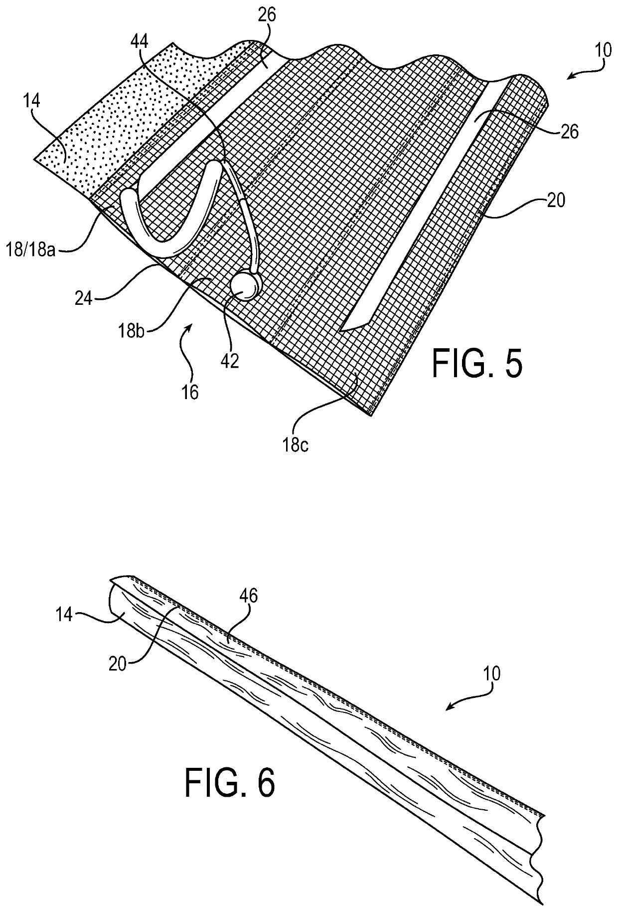
[0027]FIG. 1 is a drawing depicting an exemplary wrapped heating assembly 10 in an unwrapped position relative to a hose 12, in accordance with embodiments of the present invention. The hose 12 shown is an example, but may more generally be referred to as a tubular member 12 having any suitable configuration. For example, the tubular member 12 may have a cross-section of any suitable shape, such as for example, round, oval, polygonal or other cross sectional shape. The tubular member 12 may be made of any suitable material as are known in the art, including for example, thermosetting, thermoplastic, metallic and non-metallic materials. The tubular member may be single wall, multiple wall, reinforced or non-reinforced, and may include end fitti...


PUM


Abstract

A wrapped heating assembly may be wrapped around a tubular member for heating the tubular member. The wrapped heating assembly includes an outer insulation sleeve and a pocketed heating system that is fixed to an inner surface of the outer insulation sleeve in a manner that forms longitudinal pockets that extend between a first end of the outer insulation sleeve and a second end of the outer insulation sleeve. One or more heater strips are each respectively inserted longitudinally into a corresponding one of the pockets, wherein heat is generated by the heater strips when electrical current flows through the heater strips for heating the tubular member in a wrapped position. Multiple wrapped heating assemblies may be daisy chained together by electrical connectors into a heating system with a single thermostat and linked to a single power source to accommodate a wide range of configurations of tubular member systems.

Description

RELATED APPLICATIONS[0001]This application is a national stage application pursuant to 35 U.S.C. § 371 of PCT / US2017 / 045282 filed on Aug. 3, 2017, which claims the benefit of U.S. Provisional Application No. 62 / 375,081 filed Aug. 15, 2016, which are incorporated herein by reference.FIELD OF INVENTION[0002]This invention relates generally to heated hose assemblies, and more specifically relates to electrically heated hose configurations that prevent or minimize condensation of gases or coagulation or freezing of liquids within the hose assembly at relatively low ambient temperatures.BACKGROUND OF THE INVENTION[0003]Hoses convey liquids and gases between spaced locations. The term “hose” refers to any generally tubular, elongated member or device and includes flexible, semi-flexible and rigid devices commonly referred to as “hoses,”“tubes,”“pipes” and the like. Hoses may have different cross-sections, and may have for example, round, oval, polygonal or other cross sectional shapes. Ho...

Claims


Application Information

Patent Timeline
Patent Type & Authority Patents(United States)
IPC IPC(8): F16L53/38H05B3/34H05B3/58
CPCF16L53/38H05B3/34H05B3/58
Inventor AMOS, DAVIDHENRY, TY
Owner PARKER INTANGIBLES LLC
Learn More