Switching mode power supply circuit for three phase AC input
a power supply circuit and three-phase input technology, applied in the direction of electric variable regulation, process and machine control, instruments, etc., can solve the problems of high loss, low efficiency, more difficult and complicated than traditional single-phase boost type pfc circuits, etc., to achieve good emc solution, low cost, and high efficiency
- Summary
- Abstract
- Description
- Claims
- Application Information
AI Technical Summary
Benefits of technology
Problems solved by technology
Method used
Image

Examples
first embodiment
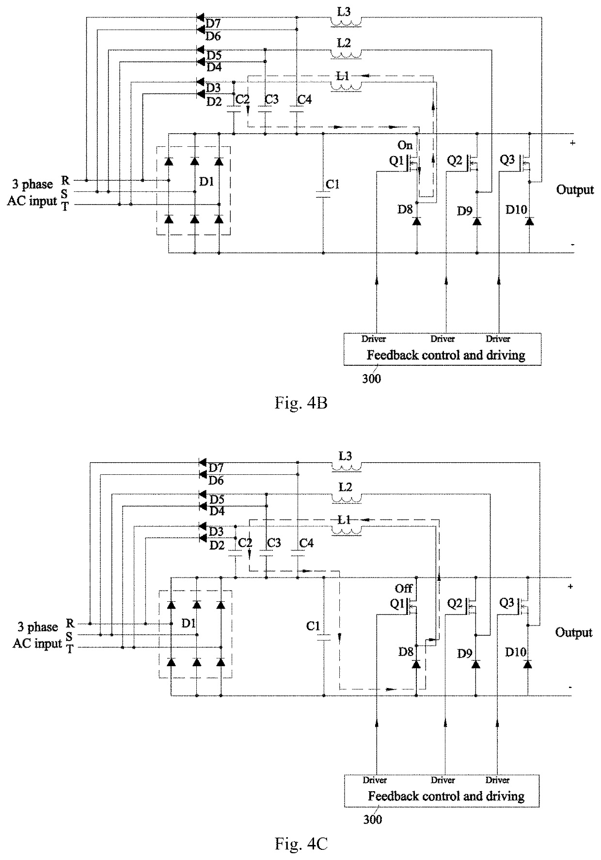
[0049]The first embodiment of three-phase input SMPS as shown in FIG. 3 comprises a first rectification circuit 101, a first capacitor C1, a boost feedback control and driving circuit 300, and a three-phase boost converter circuit 103 which includes at least one boost converter circuit. Each Boost converter circuit converts voltage of one corresponding phase of a three-phase input. In the embodiment, three identical boost converter circuits are adopted and each of the boost converter circuits connects to two corresponding poles of the three-phase input. According to this embodiment, a first boost converter circuit connects to poles R and T, a second boost converter circuit connects to poles S and T, and a third boost converter circuit connects to poles R and S. Other boost converter circuit provided in different connection to achieve the same function is also accepted.
[0050]In this embodiment, first input rectification circuit 101 is implemented as a bridge diode D1 consisting of si...
second embodiment
[0080]As shown in FIG. 5, the difference of second embodiment compared to the first embodiment lies in: an inrush current limiting circuit Rth1 coupled in series to the first loop. The inrush current limiting circuit Rth1 belongs to the first loop, but does not belong to any of the second loop the third loop or the fourth loop. Since the first loop only works at power supply's startup, the inrush current limit circuit has no loss during power supply's normal operation. Benefitting from this, Rth1 can be chosen as a normal resistor with high value to be able to withstand and effectively reduce inrush current, without sacrificing efficiency. Tradeoff between low inrush current and startup capability in traditional design is no longer required. Well-designed inrush current limiting circuit with a combination of resistor, capacitor and inductor could improve EMC surge and noise immunity. By taking advantage of the dual rectification input structure, the inrush current limiting circuit o...
third embodiment
[0082]In the third embodiment, the first output rectification circuit in each boost circuit in the above first and second embodiments is replaced by a switching component (Q4, Q5 or Q6), as shown in FIG. 6. Switching component Q4 acts as a second switching component in the first boost circuit, Q5 acts as a second switching component in the second boost circuit, and Q6 acts as a second switching component in the third boost circuit. Switching mode of the second switching components are controlled by boost feedback control and driving circuit 300. In this embodiment, both first switching component and second switching component can be designed to operate in soft switching mode, or called zero voltage switching (ZVS) mode.
[0083]In this embodiment, if first inductor operates in CCM, then first switching component operates in hard switching mode whose operating principle is same as first embodiment. Second switching component acts as boost synchronous rectification component.
[0084]If fir...
PUM
 Abstract
Description
Claims
Application Information
 - R&D
- Intellectual Property
- Life Sciences
- Materials
- Tech Scout
- Unparalleled Data Quality
- Higher Quality Content
- 60% Fewer Hallucinations
Browse by: Latest US Patents, China's latest patents, Technical Efficacy Thesaurus, Application Domain, Technology Topic, Popular Technical Reports.
© 2025 PatSnap. All rights reserved.Legal|Privacy policy|Modern Slavery Act Transparency Statement|Sitemap|About US| Contact US: help@patsnap.com