
Device and method for measuring and displaying bioelectrical function of the eyes and brain

a bioelectric function and eye technology, applied in the field of bioelectric technology, can solve the problems of data loss, time drift or lag of associated equipment, data loss, etc., and achieve the effect of reducing or eliminating these time drifts or lags, improving efficiency, and less precise clinical data

Active Publication Date: 2021-09-07
SIWOFF RONALD
View PDF4 Cites 0 Cited by
  • Summary
  • Abstract
  • Description
  • Claims
  • Application Information

AI Technical Summary

Benefits of technology

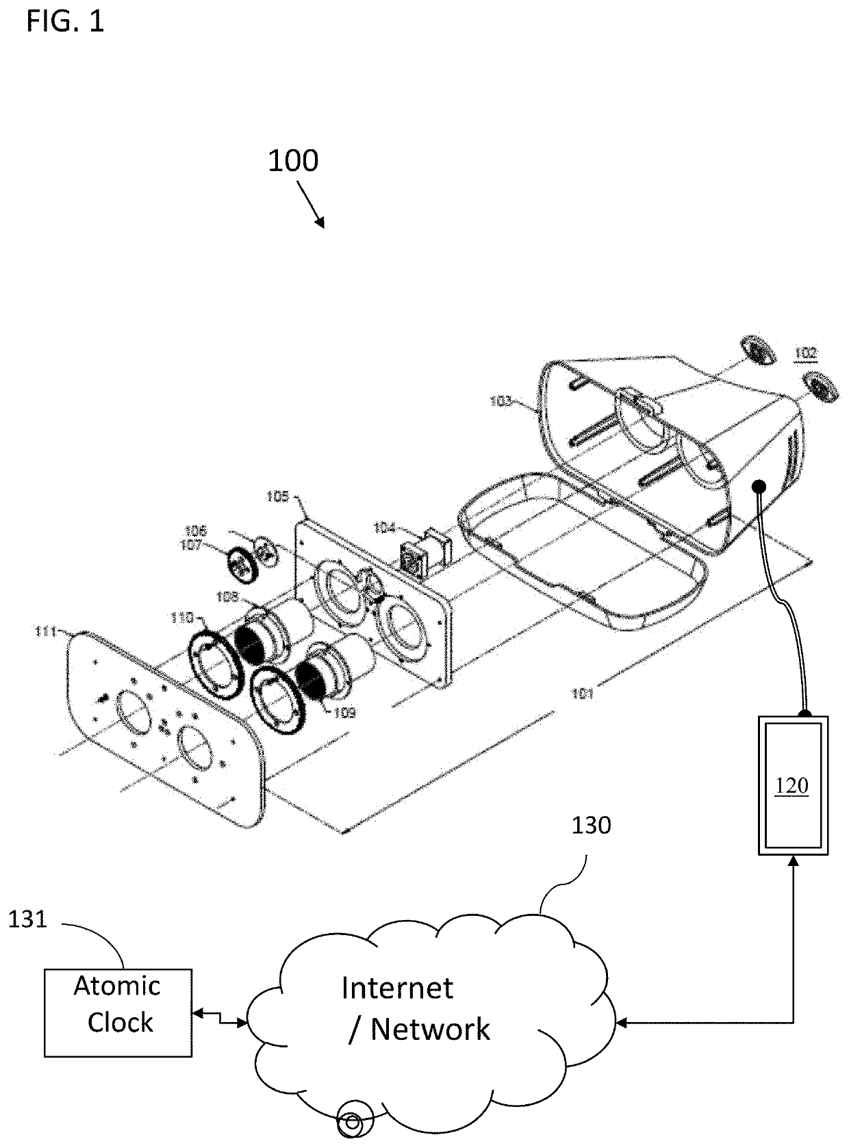
[0011]These lags, or time drifts, have been found to result in loss of data and therefore inaccurate results in the field of VEP / ERG. Time drifts or lags (e.g., due to rise and decay time) have been found to be associated with the hardware or switches used to control signal averaging of the synchronized data and / or control of the visual display device, as well as display lags associated with the time it takes the visual display device (e.g., video monitor) to display the visual stimuli once it receives the signal. Moreover, the internal clock of every computer drifts over time, making incoming timing signals differ for each CPU device, and in turn, making clinical data less precise. Improved methods, systems and computer readable mediums can be obtained by reducing or eliminating these time drifts or lags.

Problems solved by technology

Data can be lost due to input lags and / or output lags which result in time lags of the associated equipment.
These lags, or time drifts, have been found to result in loss of data and therefore inaccurate results in the field of VEP / ERG.
Moreover, the internal clock of every computer drifts over time, making incoming timing signals differ for each CPU device, and in turn, making clinical data less precise.

Method used


Image

  • Device and method for measuring and displaying bioelectrical function of the eyes and brain
  • Device and method for measuring and displaying bioelectrical function of the eyes and brain
  • Device and method for measuring and displaying bioelectrical function of the eyes and brain

Examples


example

[0112]Research Design: Researchers used a repeated measures design. This design allowed researchers to use a small sample of participants (n=10) for making statistical inference regarding the reliability of the subject system against existing equipment (i.e., Diopsys VEP device). In addition, this design allowed researchers to quickly train participants to complete those tasks required for data collection. Finally, this method allowed researchers to monitor the variance in participants' measures to generate a diagnosis of vision type using a mean measure as opposed to single measure.

[0113]Patient Selection: Five patients (“participants”) with normal vision were selected, with best corrected visual acuity of 20 / 25 or better. Each subject had no history of any eye disease and a normal eye examination. Their ages ranged from 26 to 76, with a mean of 40.6 years. Five additional patients were selected who had optic atrophy. Their diagnosis was either optic atrophy—secondary to glaucoma o...


PUM


Abstract

Apparatus, system, and computer-readable media measure electroencephalography (EEG) signals or ERG signals generated from a device that presents a series of images on a timing cycle to a subject. The apparatus comprises a Central Processing Unit (CPU), Power Supply Unit (PSU), Random Access Memory (RAM), and a hard drive (HDD). The apparatus further includes at least one electrode and a photo-sensor like a photodiode for conversion of light into electric current. The CPU is operable with software for converting the EEG or ERG signals evoked from the visual stimuli to provide data and retrieving the status of EEG signals.

Description

1. FIELD OF THE INVENTION[0001]The present invention relates to bioelectric technology used in the fields of neuro-rehabilitation, neurology, ophthalmology, and optometry; and, more particularly, to a system, apparatus, method and a computer-readable medium for extracting and processing data corresponding to electrical activity of the nervous system evoked in response to visual stimuli. The present invention further relates to both mono-focal and multi-focal applications of such systems, apparatus, method, and computer-readable medium, and to the use thereof for Visual Evoked Potential (VEP) and Electro-Retina-Gram (ERG), including Pattern Visual Evoked Potential (P-VEP) and Pattern Electro-Retinal-Gram (PERG).2. BACKGROUND[0002]There is a need in neuro-rehabilitation, neurology, ophthalmology, and optometry fields to accurately measure and extrapolate data to determine how the brain and eye process visual information. This data is utilized in vision testing, as well as in the diagn...

Claims


Application Information

Patent Timeline
Patent Type & Authority Patents(United States)
IPC IPC(8): A61B5/378A61B5/00A61B5/398
CPCA61B5/378A61B5/398A61B5/6814A61B5/6821A61B5/7285A61B5/742A61B5/7282A61B5/7289A61B5/7235A61B5/384A61B5/251A61B5/297
Inventor SIWOFF, RONALD
Owner SIWOFF RONALD
Learn More