
Cone Nut

Active Publication Date: 2015-08-20
THOMAS & BETTS INT INC
View PDF5 Cites 14 Cited by
  • Summary
  • Abstract
  • Description
  • Claims
  • Application Information

AI Technical Summary

Benefits of technology

The present invention is an improved cone nut for a structural channel that uses a friction fit locking mechanism to attach a cone to a channel nut, eliminating the need for glue. This friction fit of the cone to the channel nut results in a stronger and more reliable connection, reducing the risk of failure due to insufficient strength of glue. The invention also saves time and provides ease of installation as a tedious gluing process is not required. Additionally, the invention eliminates errors resulting from the amount of glue used and ensures the cone remains securely attached to the channel nut, preventing failure that would render the channel nut useless.

Problems solved by technology

During installation and use, it is possible that the cone can become detached from the nut portion, rendering the channel nut useless.
Detachment of the cone from the nut portion can also result from failed glue strength in instances where the cone has been glued to the channel nut.
Attempts to form the cone out of harder material results in superior attachment of the cone to the channel nut, but renders installation of the channel nut more difficult as more manual force is needed.
Again, if the cone has been glued to the nut portion, the required extra manual force needed to effect installation of the channel nut can result in failure of the glue strength which holds the cone to the nut.

Method used


Image

  • Cone Nut
  • Cone Nut
  • Cone Nut

Examples


Embodiment Construction

)

[0020]The above and other features, aspects and advantages of the present invention will now be discussed in the following detailed description of preferred embodiments and appended claims, which are to be considered in conjunction with the accompanying drawings in which identical reference characters designate like elements throughout the views.

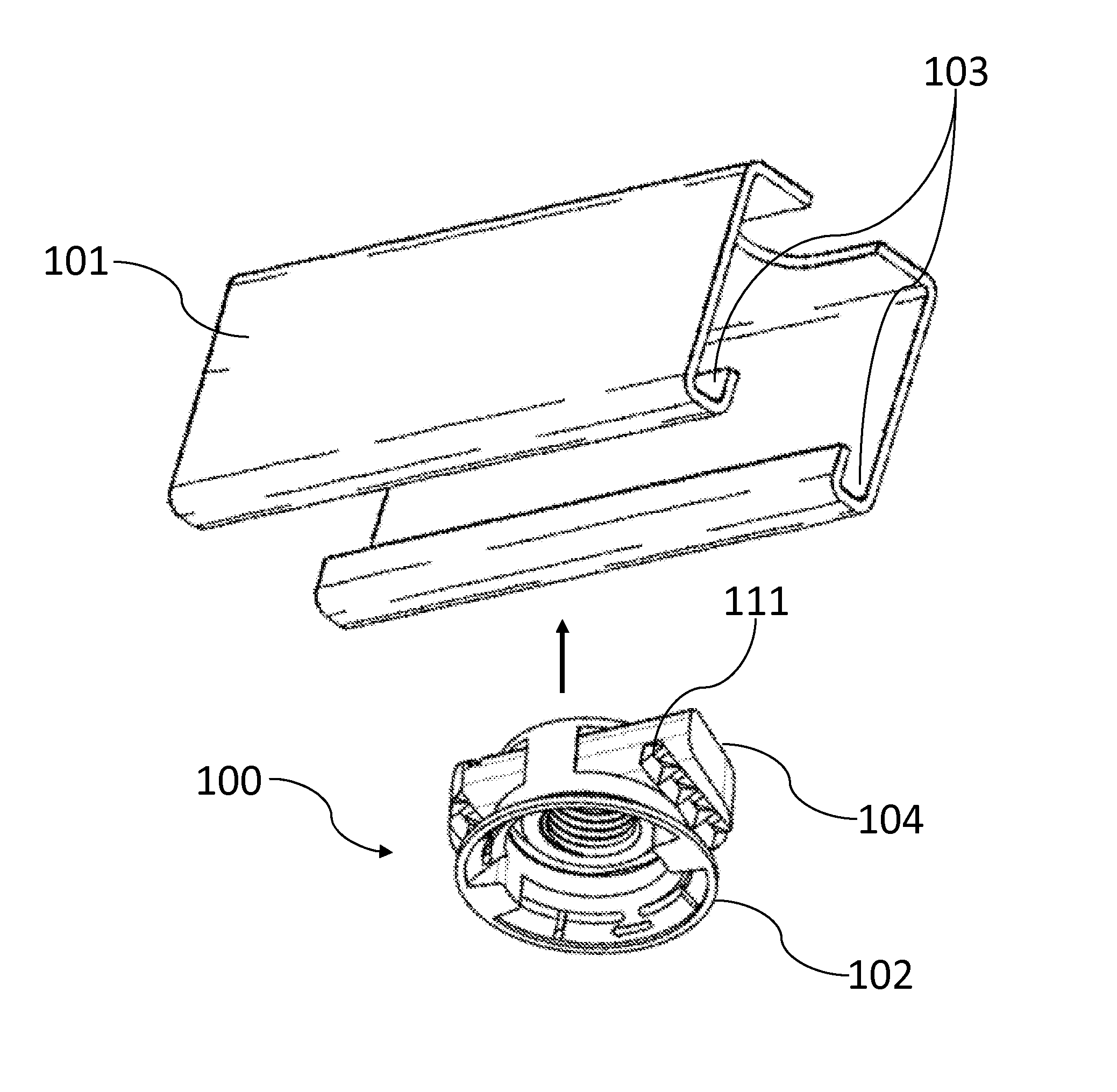
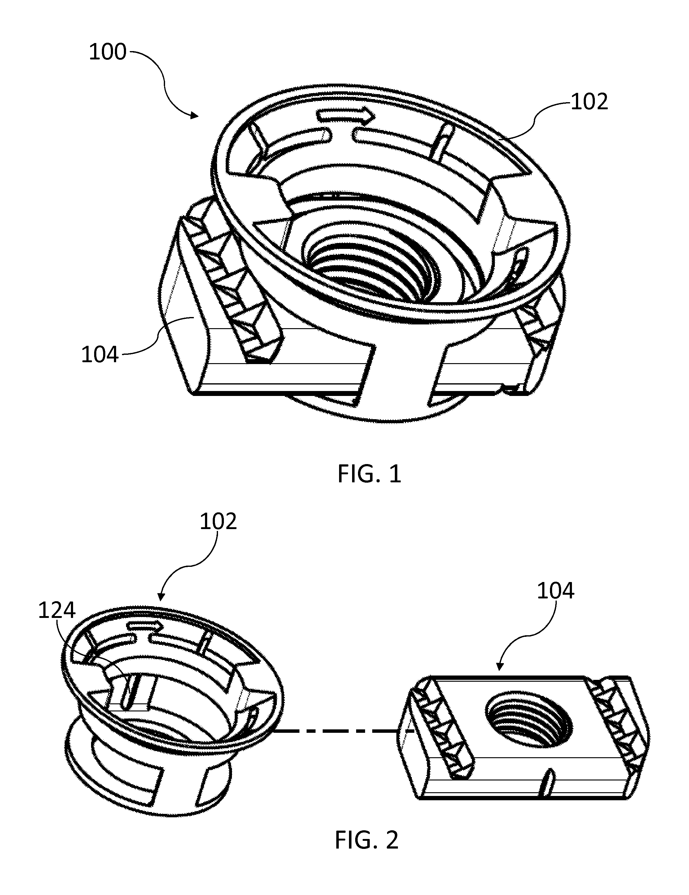
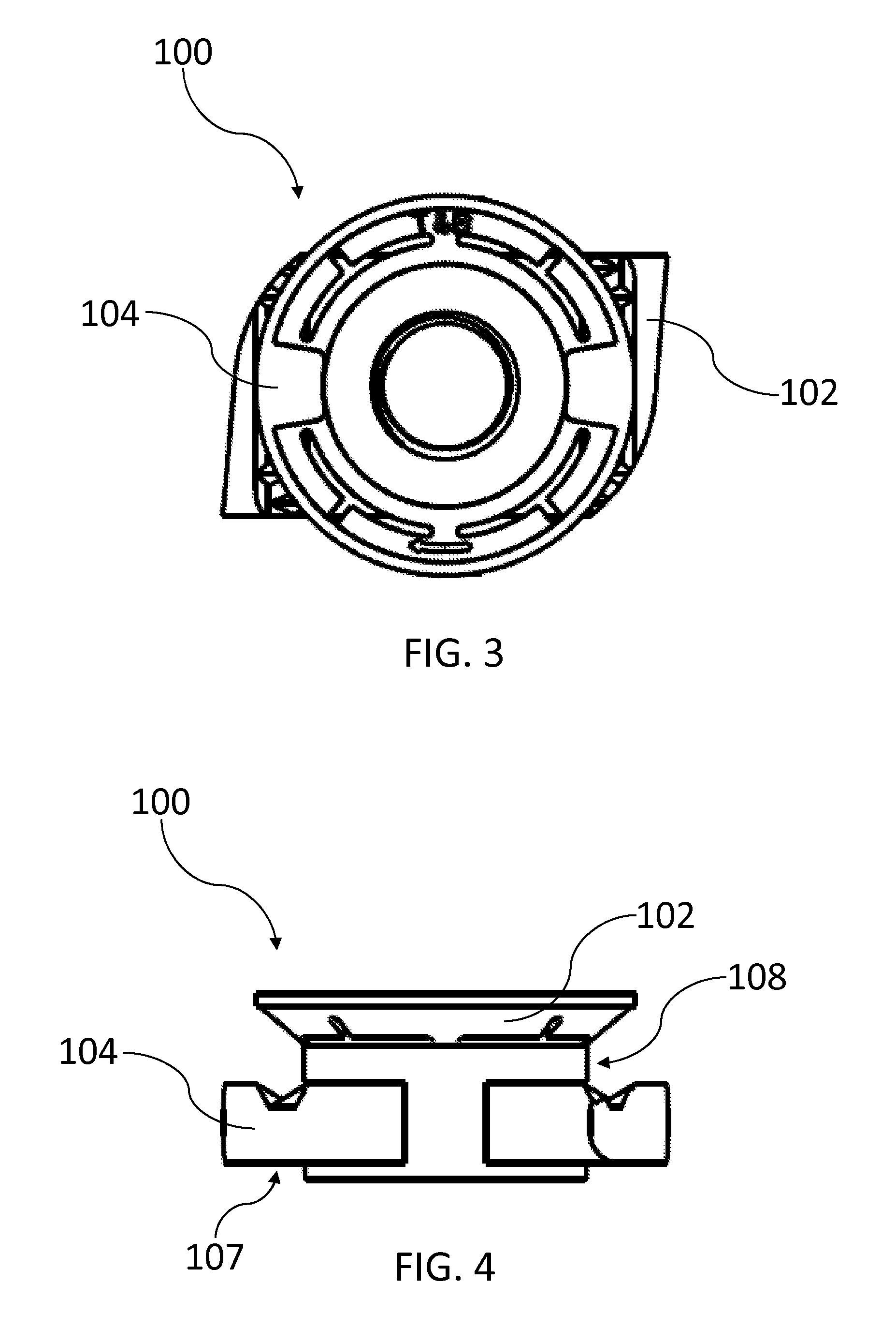
[0021]Shown in FIG. 1 is a front perspective view of a cone nut 100 of the present invention. The cone nut 100 is comprised of a flexible cone 102 and a channel nut 104. It is preferable that the flexible cone 102 is made of nylon and the channel nut 104 is made of metal, but it is understood that other materials may be chosen. FIG. 2 shows that the cone nut 100 is fully assembled when the cone 102 receives the channel nut 104. The channel nut 104 is received through a cone attachment portion 108 of the cone 102, as shown in FIG. 4.

[0022]The cone attachment portion 108 surrounds the channel nut 104 on four sides: a planar surface 106 (shown...


PUM


Abstract

An improved cone nut for a structural channel is provided. The cone nut does not require gluing of the cone to the channel nut as in conventional methods. The cone instead houses the channel nut by a friction fit locking mechanism, resulting in a secure attachment of the cone to the channel nut which prevents failure of the cone by separation from the channel nut which would, in turn, render the channel nut useless.

Description

FIELD OF THE INVENTION[0001]In general, the present invention relates to an improved cone nut for a structural channel which does not use conventional gluing techniques and which has an improved design to eliminate cone failure in order to keep the nut securely fastened within the channel.BACKGROUND[0002]Elongate structural members have long been used for various purposes in the construction industry. These structural members, which are commonly referred to as struts, include an elongate channel having a generally U-shaped configuration. The lower edges of the U-shaped channel include inwardly turned flanges or shoulders extending along the length thereof. These inwardly turned shoulders support fastening hardware which allows for the attachment of various loads which may be supported by the struts.[0003]In order to permit attachment of loads to the strut, a threaded fastener or nut is positioned within the channel of the strut and secured thereto. Channel nuts of this type are show...

Claims


Application Information

Patent Timeline
IPC IPC(8): F16B37/04
CPCF16B37/046
Inventor PARTHIBHAN, SURESH KUMARREAGAN, CHRISTINE S.
Owner THOMAS & BETTS INT INC
Learn More