Method and control device for monitoring the function of a particulate filter

a technology of particulate filter and control device, which is applied in the direction of electrical control, machine/engine, separation process, etc., can solve the problem of not being able to directly measure the soot concentration in the exhaust gas, and achieve the effect of avoiding the risk of data loss due to the conversion steps, reducing the number of conversion steps, and simplifying the diagnostics of the functionality of the diesel particulate filter

Active Publication Date: 2021-08-31
ROBERT BOSCH GMBH
View PDF18 Cites 0 Cited by
  • Summary
  • Abstract
  • Description
  • Claims
  • Application Information

AI Technical Summary

Benefits of technology

[0012]The problem of the invention is solved in regard to the method in that the simulated soot emission is determined as being a simulated soot particle concentration at the installation site of the particle sensor. Thanks to the model approach, a repeated converting of soot concentrations into soot mass flows and back to soot concentrations is avoided. Furthermore, the risk of data loss due to the conversion steps can be avoided. Thus, the diagnostics for the functionality of the Diesel particulate filter are simplified. A further benefit of the sole use of concentration values throughout is a good correlation between the soot concentration and other exhaust gas variables, making a model approach easier. This also has a beneficial effect on reducing the number of characteristic curves and characteristic maps, as well as the overall computing expense. The procedure therefore reduces the parametrization expense and the computing time.
[0014]A control device or arithmetic unit according to the invention, e.g., a controller of a motor vehicle, is designed, in particular by programming, to carry out a method according to the invention. In the control device a program sequence or a circuit for the simulation of a soot particle concentration as the simulated soot emission at the installation site of the particle sensor can be provided. The control unit can be simplified in its structure thanks to the reduced computational expense.
[0015]The implementing of the method in the form of a computer program is also advantageous, since this produces particularly low costs, especially if a controller executing it is also used for further tasks and therefore would be present in any case. Suitable data media for the providing of the computer program are in particular magnetic, optical and electrical storage media, such as hard disks, flash memories, EEPROMs, DVDs and so forth. A downloading of a program through computer networks (Internet, intranet, etc.) is also possible.

Problems solved by technology

Due to the functional principle of the collecting particle sensor, it cannot directly measure the soot concentration in the exhaust gas.

Method used


Image

  • Method and control device for monitoring the function of a particulate filter
  • Method and control device for monitoring the function of a particulate filter
  • Method and control device for monitoring the function of a particulate filter

Examples


Embodiment Construction

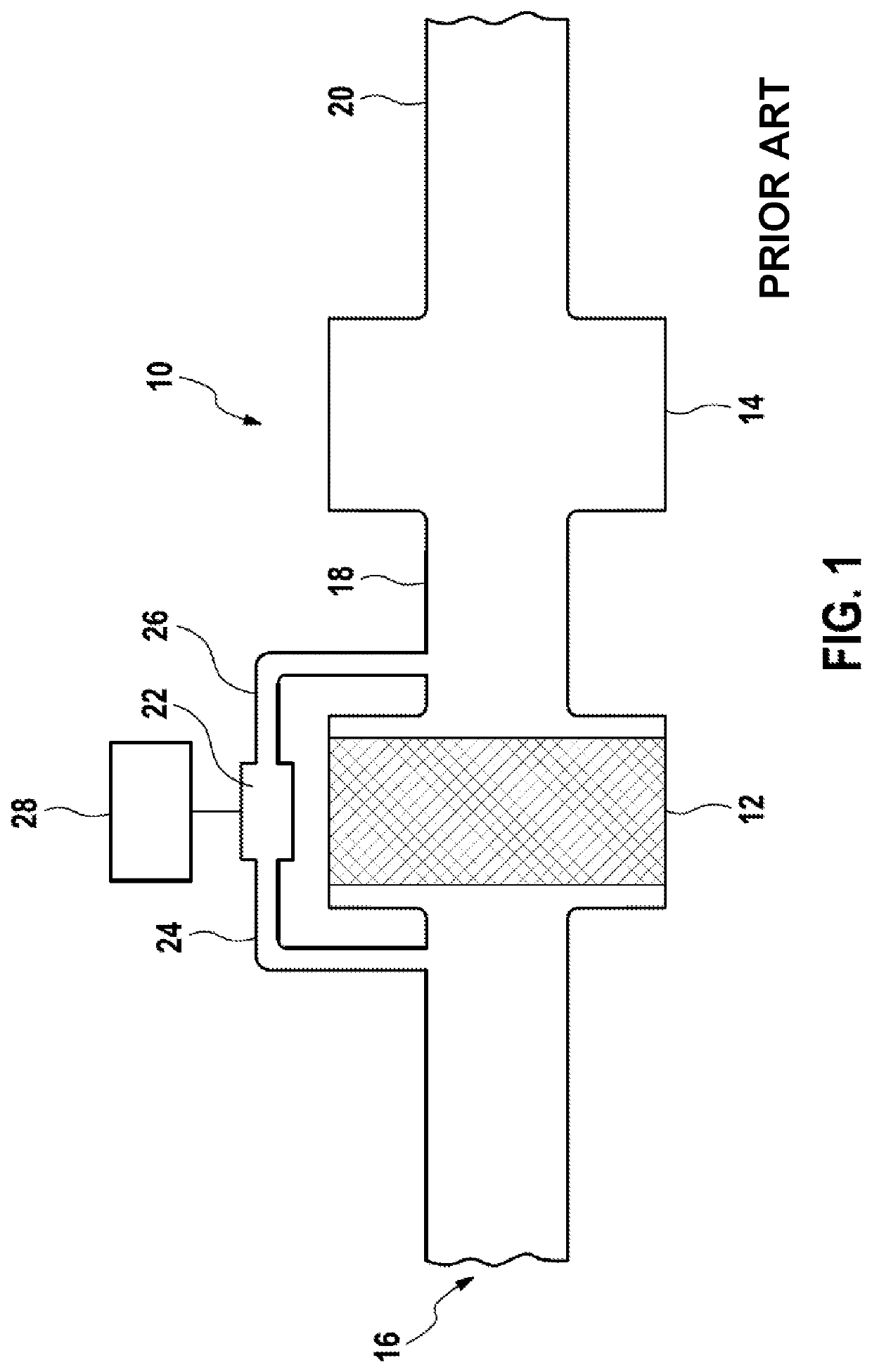
[0020]The prior art is soot simulation on the basis of soot particle mass flows by various techniques. The drawback to this method is that it requires a double converting of a concentration, which is typically determined by mensuration, into a mass flow, obtained on the basis of a model, and back to a concentration, which is the basis of a diagnostic function for assessing whether the DPF is good or defective. This is costly in computing time and carries the risk of data loss during the conversions.

[0021]FIG. 1 shows schematically an exhaust gas system 10 with a particulate filter 12 and a muffler 14. Exhaust gases from an internal combustion engine (not shown) are taken through an exhaust gas supply 16 to the particulate filter 12, flow through the particulate filter 12, then flow through an exhaust gas connecting pipe 18, then through the muffler 14, and are then put out to the surroundings through the exhaust gas discharge 20. In modern internal combustion engines, the combustion...


PUM

PropertyMeasurementUnit
concentrationaaaaaaaaaa
soot concentration modelaaaaaaaaaa
rotational speedaaaaaaaaaa

Abstract

A method and control device for monitoring the function of a particulate filter in an exhaust gas duct of an internal combustion engine. A soot emission in the exhaust gas duct downstream from the particulate filter is determined with a particle sensor, an expected soot emission after a limit particulate filter at the location of the particle sensor is simulated and a comparison value is ascertained. A good particulate filter is found if the measured soot emission is less than the comparison value of the simulated soot emission. A defective particulate filter is found if the measured soot emission is higher than the comparison value of the simulated soot emission. The simulated soot emission is determined as being a simulated soot particle concentration at the installation site of the particle sensor such that a basic soot concentration in a soot concentration model is corrected at least with an oxygen correction.

Description

BACKGROUND OF THE INVENTION[0001]The invention relates to a method for monitoring the function of a particulate filter, especially a Diesel particulate filter, in an exhaust gas duct of an internal combustion engine, wherein a soot emission in the exhaust gas duct downstream from the Diesel particulate filter is determined with a particle sensor, wherein an expected soot emission after a limit particulate filter at the location of the particle sensor is simulated and wherein a good particulate filter is found if the measured soot emission is less than the simulated soot emission and a defective particulate filter is found if the measured soot emission is higher than the simulated soot emission.[0002]The invention moreover relates to a control device for monitoring the function of a particulate filter, especially a Diesel particulate filter, in an exhaust gas duct of an internal combustion engine, wherein a particle sensor is provided in the exhaust gas duct downstream from the parti...

Claims


Application Information

Patent Timeline
Patent Type & Authority Patents(United States)
IPC IPC(8): B01D46/44F02D41/14F01N11/00F02D41/02F01N3/021
CPCF02D41/1466B01D46/442F01N3/021F01N11/007F02D41/0235F01N2550/04F02D2200/0812F02D2200/101F02D2200/1002F02D2200/703F01N11/00F01N2900/16F01N13/008F01N2560/025F01N2560/05F01N2900/0402F01N2900/0412F01N2900/1402F01N2900/1606F02D41/0072F02D41/1454F02D41/1467F02M26/46Y02T10/12Y02T10/40F02D41/1401F02D2041/1433F02D2200/10
Inventor HERBERGER, PATRIK
Owner ROBERT BOSCH GMBH
Why Eureka
Try Eureka