
Controller unit for controlling the speed of a motor driving an oil injected compressor and method of controlling said speed

a technology of controller unit and compressor, which is applied in the direction of liquid fuel engines, lighting and heating apparatus, instruments, etc., can solve the problems of not being able to achieve the solution of an existing unit without the need of considerable work and costs, and the formation of condensate within the oil injected compressor is a known problem, etc., and achieves the effect of convenient implementation

Active Publication Date: 2021-08-17
ATLAS COPCO AIRPOWER NV
View PDF18 Cites 2 Cited by
  • Summary
  • Abstract
  • Description
  • Claims
  • Application Information

AI Technical Summary

Benefits of technology

The invention aims to find a solution that prevents condensate formation in an oil injected compressor by an easy-to-implement method. The proposed solution is cost-effective and can improve the efficiency of existing units without significant intervention or increased maintenance costs. Ultimately, the solution will lead to a longer lifetime for the compressor and its components, as well as the oil used in the process.

Problems solved by technology

The condensate formation within an oil injected compressor is a known problem.
If such condensate is allowed to form it can damage the quality of oil injected therein or even the casing or the compressor element due to its corrosive effects.
While such a proposed method provides a valid solution for overcoming the problem, the piping and the overall structure of the compressor would have to be decided upon its design, such a solution not being feasible for an existing unit without the need of considerable work and costs.
Another aspect worth considering is the complexity of the overall design once such method is implemented, such complexity having an impact on the frequency of the maintenance process and its costs.

Method used


Image

  • Controller unit for controlling the speed of a motor driving an oil injected compressor and method of controlling said speed
  • Controller unit for controlling the speed of a motor driving an oil injected compressor and method of controlling said speed

Examples


Embodiment Construction

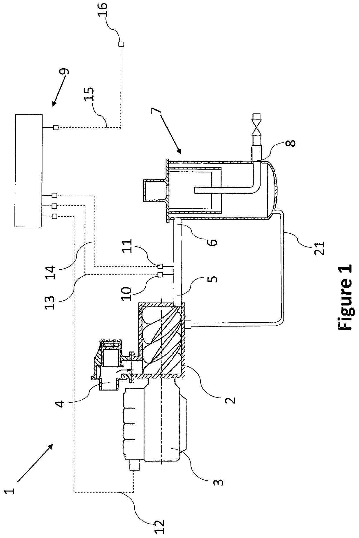
[0036]FIG. 1 illustrates an oil injected compressor 1 comprising at least a compressor element 2 driven by a motor 3. The compressor element 2 having an air inlet 4 through which air at atmospheric pressure is drawn in and a compressed air outlet 5.

[0037]The compressed air outlet 5 being further in fluid communication with the inlet 6 of an oil separator 7, wherein the oil is removed from the compressed air.

[0038]The oil separator 7 further comprises an outlet conduit 8 through which purified compressed air is supplied to a user's network (not shown).

[0039]The oil removed from the compressed air within the oil separator 7 can be further re-injected in the compressor element 2 for lubrication and cooling purposes.

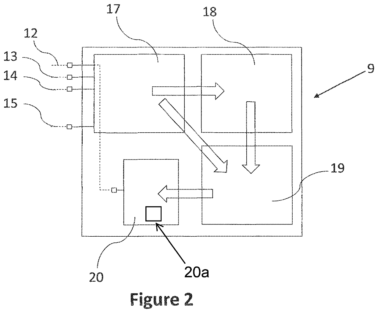
[0040]The oil injected compressor 1 further comprises a controller unit 9, receiving measurement data from measurement means 10 and 11, positioned on the compressed air outlet 5.

[0041]The controller unit 9 preferably further comprises a data connection 12 with the motor 3 fo...


PUM


Abstract

A controller unit for controlling the speed of a motor for driving an oil injected compressor, the controller unit including: a data connection; and a first module to receive data through the data connection. The controller unit includes a processing unit for determining a minimum working speed of the motor on the basis of the measured working pressure, the ambient temperature and a dew point temperature; and a comparator unit to compare the determined minimum working speed with the retrieved working speed of the motor. The processing unit includes a signal generating unit to send a signal to the motor for increasing the working speed of the motor to at least the determined minimum working speed, if the retrieved working speed is lower than the determined minimum working speed.

Description

[0001]This invention relates to a controller unit for controlling the speed of a motor for driving an oil injected compressor, said controller comprising: a data connection configured to connect the controller unit with measuring means; a first module configured to receive data through said data connection, wherein said data comprises: a measurement of a working pressure of said compressor and a working speed of the motor, said first module further being configured to receive a measured or retrieved ambient temperature value.BACKGROUND OF THE INVENTION[0002]The condensate formation within an oil injected compressor is a known problem. If such condensate is allowed to form it can damage the quality of oil injected therein or even the casing or the compressor element due to its corrosive effects.[0003]One proposed method of avoiding such risks is the control of the temperature within the compressor by adjusting the flow of injected oil through a mixing valve, as proposed in WO 2007 / 04...

Claims


Application Information

Patent Timeline
Patent Type & Authority Patents(United States)
IPC IPC(8): F04C29/00F04C29/02G05D23/19
CPCF04C29/0014F04C29/026G05D23/1951F04C2270/185F25B2600/02F25B2700/151F25B2700/171F04B49/06F04B49/065F04C18/0215F04C18/16F04C28/08F04C28/28F04C2210/1005F04C2210/221F04C2270/18F04C2270/19F05B2210/12F05B2210/16F05B2270/3013F05B2270/303F04B49/20
Inventor MOENS, WIM
Owner ATLAS COPCO AIRPOWER NV
Learn More