Relating to a respiratory device

a technology for respiratory devices and sensors, applied in the field of respiratory devices, can solve the problems of water seeping between parts, damage to electronic components within the device, and difficulty in servicing these sensors, so as to improve the ability to access, facilitate manipulation of lids, and improve the effect of access

Active Publication Date: 2021-08-10
FISHER & PAYKEL HEALTHCARE LTD
View PDF15 Cites 0 Cited by
  • Summary
  • Abstract
  • Description
  • Claims
  • Application Information

AI Technical Summary

Benefits of technology

[0006]CPAP machines include an airflow generator to supply pressurized gas to a user. Many CPAP machines include a heated water bath or other source of water for humidification of the pressurized gas. CPAP machines are often used in bedrooms or other sleeping quarters and are placed on nightstands, for example. As such, it may be desirable for the CPAP machine to look aesthetically pleasing. It may also be desirable for the CPAP machine to be substantially stable when placed on a supporting surface, such as on a nightstand. It may also be desirable for CPAP machines to be easily refilled with water, and to be moved when containing water, with minimum risk of spills that may cause water damage to the sensitive electronic components within the machine. CPAP machines may also need to be serviced from time to time and so it may be useful for the key components of the machine to be readily accessible for servicing.
[0026]Because of the cramped spaces in which CPAP machines are used, easy manipulation of a lid or other component used to enclose a water reservoir or the like is desired. Preferably, the lid or other such component can be easily pivoted about hinges.
[0027]Moreover, to improve the ability to access the water reservoir, the lid preferably carries a locking mechanism that is configured to allow a user to release the lock and open the lid with a single hand, preferably, with the single hand in a single position. Such configurations are a welcomed improvement over configurations requiring one hand to operate the lock and another hand to subsequently raise the lid.

Problems solved by technology

Where the device is formed of many separate parts, there is a risk that water could seep between parts and damage electronic components within the device.
In some configurations, the breathing treatment devices may comprise one or more sensors at various locations within the device, which may make it difficult to service these sensors.

Method used


Image

  • Relating to a respiratory device
  • Relating to a respiratory device
  • Relating to a respiratory device

Examples


Embodiment Construction

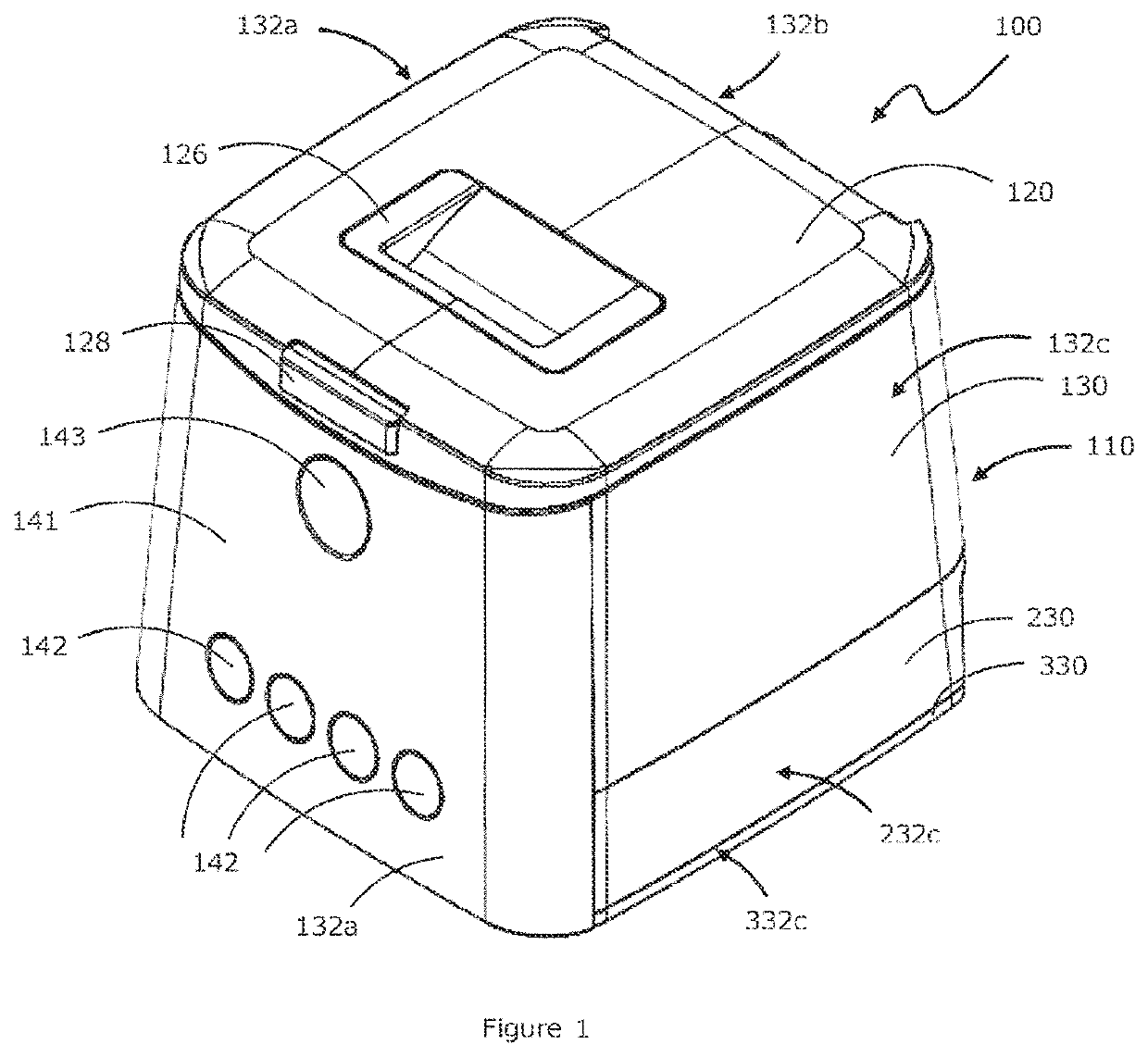
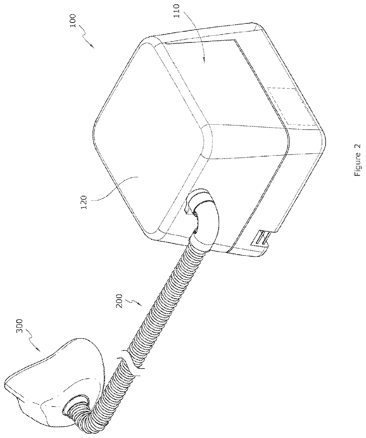
[0051]FIG. 1 illustrates a breathing assistance apparatus 100 that is arranged and configured in accordance with certain features, aspects and advantages of the present invention. FIG. 2 shows one form of breathing assistance apparatus 100 connected to a breathing tube 200 and an interfacing structure 300. In the embodiment illustrated, the interfacing structure 300 is a mask, but the breathing assistance apparatus 100 of the invention may be used with any suitable form of interfacing structure, including a nasal cannula or nasal pillows, for example.

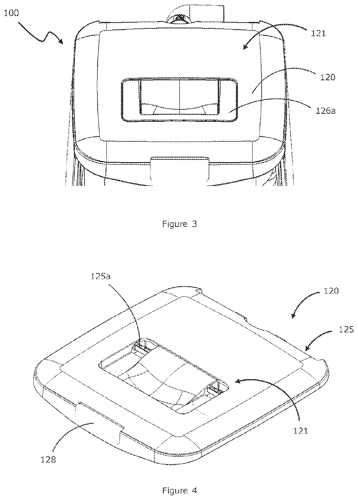
[0052]In one form, as shown in FIGS. 1 to 21, the breathing apparatus 100 is a CPAP machine that includes a housing comprising a body 110 and a lid 120. The body 110 may be configured to house a humidification chamber with water reservoir, a heating element, a blower, and an electronic system that connects a user interface to electronic components of the CPAP machine 100.

[0053]In one form, as shown in FIG. 1, the body 110 may comprise a...


PUM


Abstract

A breathing assistance apparatus that comprises a housing with inner and outer walls and an upper surface, wherein the walls and upper surface are integrally formed as a single part to avoid seams or joins between the walls to reduce the risk of damage to electronics within the apparatus as a result of liquid leaks. Also disclosed is a control system for a heating element of a humidifier which provides a secondary or back up protection mechanism to disable power to the heating element if a first electronic protection circuit does not cause the first switching member to disable power to the heating element.

Description

BACKGROUND OF THE INVENTIONField of the Invention[0001]The present invention generally relates to respiratory devices. More particularly, the present invention relates to respiratory devices for humidifying breathing gases.Description of the Related Art[0002]Breathing treatment devices typically include an airflow generator to supply pressurized breathing gases. In some breathing treatment devices, an integrated water supply chamber may be provided. The water chamber can include a supply of water that is used to humidify the breathing gases that are being supplied by the breathing treatment device.[0003]In some configurations, the breathing treatment devices are designed to be portable and / or movable. When such devices are moved while containing water in a water supply reservoir, the reservoir may tip and allow water to spill from the water reservoir into other regions of the breathing treatment devices. Where the device is formed of many separate parts, there is a risk that water c...

Claims


Application Information

Patent Timeline
Patent Type & Authority Patents(United States)
IPC IPC(8): A61M16/10A61M16/16A61M16/00
CPCA61M16/109A61M16/0066A61M16/0087A61M16/161A61M2205/3372A61M16/0816A61M16/0875A61M16/16A61M2016/0027A61M2205/3368A61M2206/14A61M16/024A61M2205/502A61M2205/3606
Inventor WRIGHT, DOUGLAS RICHARDGRYLLS, PETER LAWRENCESALMON, ANDREW PAUL MAXWELLDICKINSON, PHILIP JOHNSUN, YI-CHENGBUTLER, SILVAN TERENCEFILIP, SERGIU CONSTANTINSAUNDERS, SAMUEL WILLIAMLETTON, ANDREW MARTIN
Owner FISHER & PAYKEL HEALTHCARE LTD
Why Eureka
Try Eureka