Inductor bridge and electronic device
a technology of electronic devices and bridges, applied in the field of elements, can solve the problems of poor connection between the joining portion and the circuit portion, the inductance of the inductance of the coil is significantly reduced or prevented, and the inductance of the coil is not only bending, so as to achieve the effect of increasing the connection reliability, reducing the deviation of reducing the inductance of the coil significantly
- Summary
- Abstract
- Description
- Claims
- Application Information
AI Technical Summary
Benefits of technology
Problems solved by technology
Method used
Image
Examples
first preferred embodiment
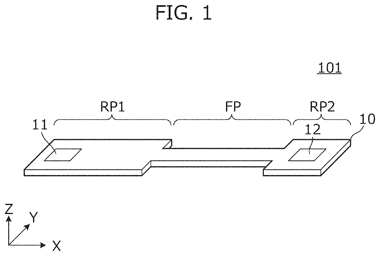
[0027]FIG. 1 is an external perspective view of an inductor bridge 101 according to a first preferred embodiment of the present invention. The inductor bridge 101 includes a flexible substrate 10 and a coil defined by a conductor pattern provided on or in the flexible substrate 10, and connects a plurality of circuit portions.
[0028]The flexible substrate 10 includes wide rigid portions RP1 and RP2 and a narrow flexible portion FP. That is, the rigid portions RP1 and RP2 are wider than the flexible portion FP. In FIG. 1, the direction along the Y axis is the width direction. A first joining portion 11 is provided on the rigid portion RP1 of the inductor bridge 101, and a second joining portion 12 is provided on the rigid portion RP2.
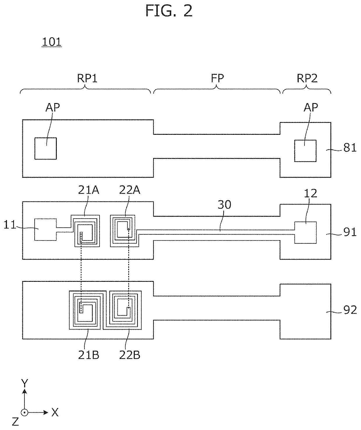
[0029]FIG. 2 is a plan view of each layer of the inductor bridge 101. The inductor bridge 101 includes insulating base material layers 91 and 92 and a resist film 81. On the insulating base material layer 91, a first joining portion 11, a first coil porti...
second preferred embodiment
[0036]In a second preferred embodiment of the present invention, an example of an inductor bridge including a coil different from that of the first preferred embodiment will be described.
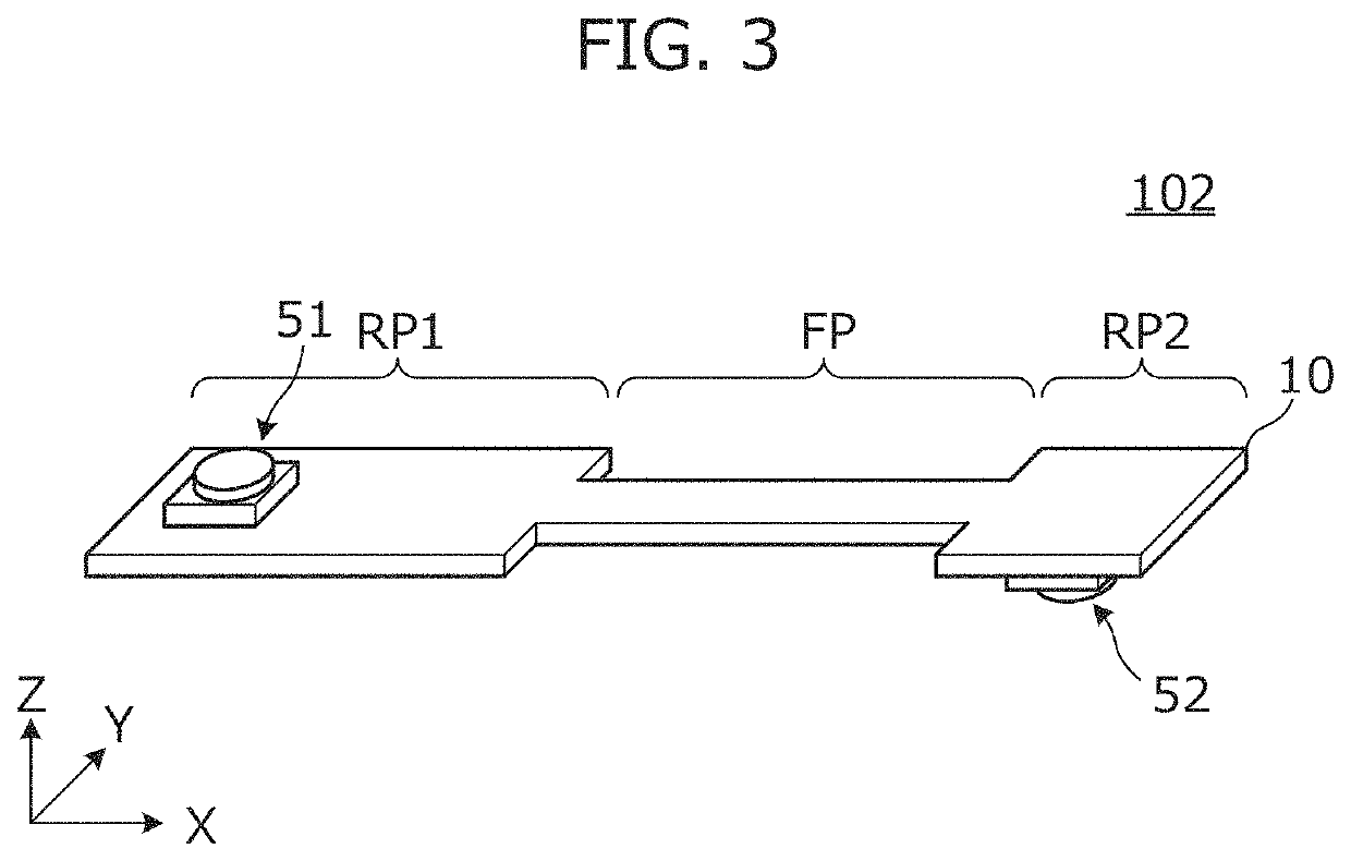
[0037]FIG. 3 is an external perspective view of the inductor bridge 102 according to the second preferred embodiment. The inductor bridge 102 includes a flexible substrate 10 and a coil defined by a conductor pattern provided on or in the flexible substrate 10, and connects two circuit portions. The inductor bridge 102 includes connectors 51 and 52. The connector 51 is joined to a first joining portion, which will be described later. The connector 52 is joined to a second joining portion, which will be described later.
[0038]FIG. 4 is a plan view of each layer of the inductor bridge 102. The inductor bridge 102 includes insulating base material layers 91 and 92 and resist films 81 and 82. A first joining portion 11, a first coil portion 21A, and a second coil portion 22A are provided in the rigid por...
third preferred embodiment
[0048]In a third preferred embodiment of the present invention, an example of an inductor bridge including a coil that is different from that of the first and second preferred embodiments will be described.
[0049]FIG. 7 is a plan view of each layer of an inductor bridge according to the third preferred embodiment. Further, FIG. 8 is a longitudinal cross-sectional view of the inductor bridge 103. The inductor bridge 103 includes insulating base material layers 91, 92, 93 and 94. A first joining portion 11, a first coil portion 21A, and a second coil portion 22A are provided in a rigid portion RP of the insulating base material layer 91. An internal electrode 11S of a first joining portion, a first coil portion 21B, and a second coil portion 22B are provided in a rigid portion RP of the insulating base material layer 92. An internal electrode 11S of a first joining portion, a first coil portion 21C, and a second coil portion 22C are provided in a rigid portion RP of the insulating base...
PUM
| Property | Measurement | Unit |
|---|---|---|
| flexible | aaaaa | aaaaa |
| inductance | aaaaa | aaaaa |
| magnetic flux | aaaaa | aaaaa |
Abstract
Description
Claims
Application Information
 - R&D
- Intellectual Property
- Life Sciences
- Materials
- Tech Scout
- Unparalleled Data Quality
- Higher Quality Content
- 60% Fewer Hallucinations
Browse by: Latest US Patents, China's latest patents, Technical Efficacy Thesaurus, Application Domain, Technology Topic, Popular Technical Reports.
© 2025 PatSnap. All rights reserved.Legal|Privacy policy|Modern Slavery Act Transparency Statement|Sitemap|About US| Contact US: help@patsnap.com


