Display device

a display device and display technology, applied in the field of display devices, can solve the problems of increasing power consumption, increasing electromagnetic interference (emi), increasing power consumption, and increasing emi

Active Publication Date: 2021-07-20
LG DISPLAY CO LTD
View PDF10 Cites 1 Cited by
  • Summary
  • Abstract
  • Description
  • Claims
  • Application Information

AI Technical Summary

Benefits of technology

[0012]In various embodiments, the present disclosure provides a display device capable of minimizing transition of signals transmitted from a timing controller to a level shifter IC.

Problems solved by technology

However, since the on clock and the off clock are transmitted by successively repeated signal transition, power consumption increases and electromagnetic interference (EMI) increases.
As such, since the three pairs of on clocks and off clocks, which successively repeat signal transition, are transmitted from the timing controller to the level shifter IC, power consumption increases and EMI also increases.

Method used


Image

  • Display device
  • Display device
  • Display device

Examples


first embodiment

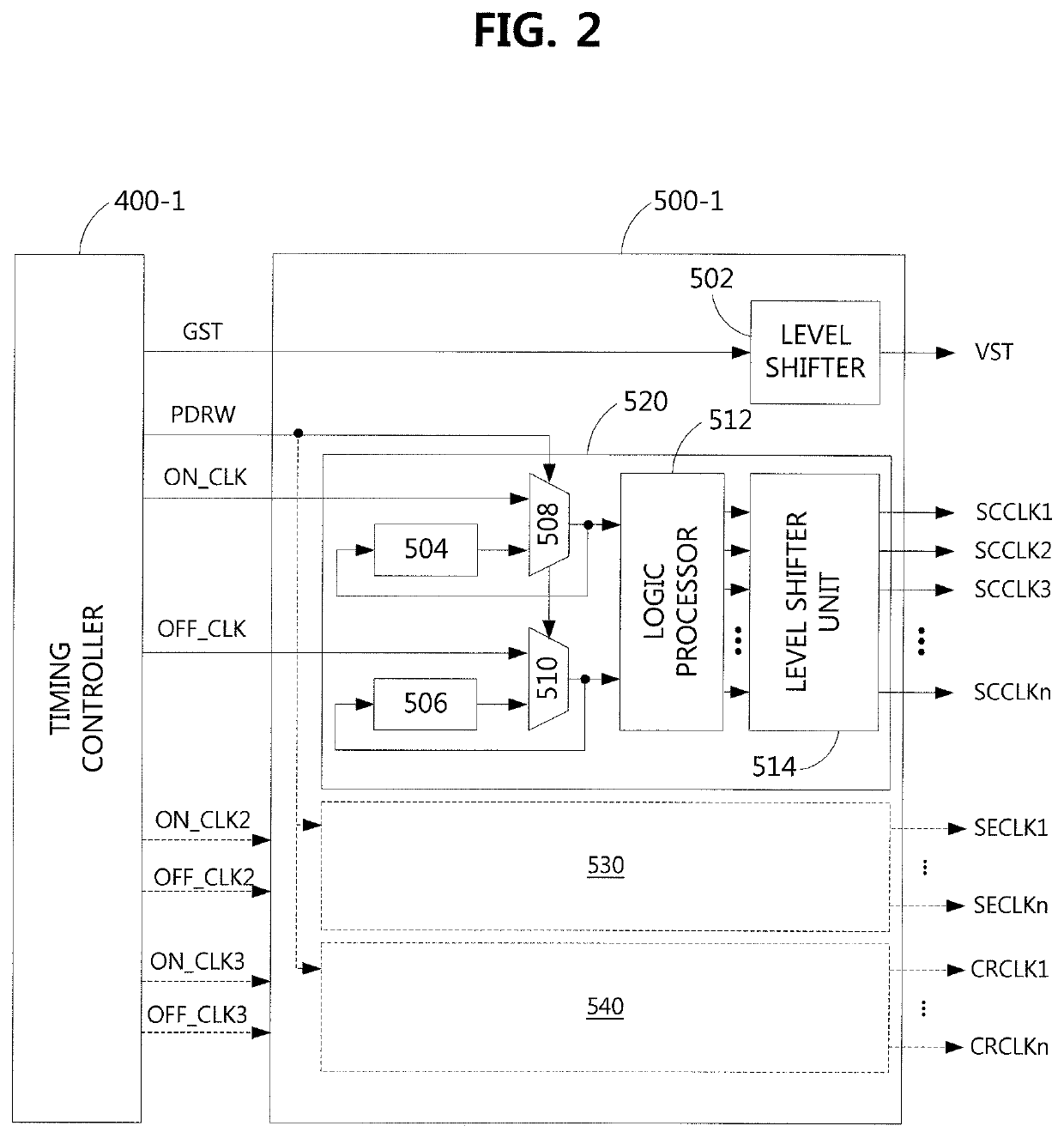
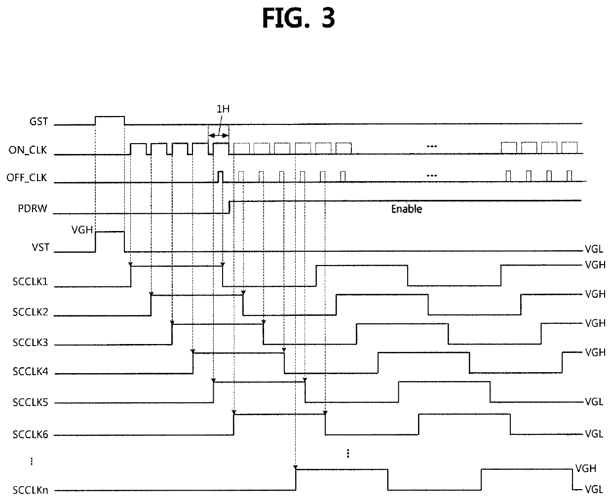
[0054]FIG. 2 is a block diagram of a timing controller and a level shifter IC according to the present disclosure. FIG. 3 is a timing chart of input and output signals of the level shifter IC illustrated in FIG. 2.

[0055]Referring to FIG. 2, a level shifter IC 500-1 can include a level shifter 502 and a scan clock generator 520.

[0056]Referring to FIGS. 2 and 3, the level shifter 502 level-shifts a first start pulse GST received from a timing controller 400-1 and outputs a second start pulse VST having a gate-on voltage VGH and a gate-off voltage VGL to the gate driver 200.

[0057]The scan clock generator 520 generates and level-shifts a plurality of scan clocks SCCLK1 to SCCLKn using an on clock ON_CLK and an off clock OFF_CLK, which are received from the timing controller 400-1 or buffered therein according to a PDRW control signal received from the timing controller 400-1, and the scan clock generator 520 outputs the level-shifted scan clocks to the gate driver 200.

[0058]The scan clo...

second embodiment

[0069]FIG. 4 is a block diagram of a timing controller and a level shifter IC according to the present disclosure. FIG. 5 is a timing chart of input and output signals of the level shifter IC illustrated in FIG. 4. FIG. 6 is a flowchart illustrating a scan clock generation method of a level shifter IC according to an embodiment of the present disclosure.

[0070]A level shifter IC 500-2 illustrated in FIG. 4 according to the second embodiment of the present disclosure is different from the level shifter IC 500-1 illustrated in FIG. 2 according to the first embodiment of the present disclosure in that the PDRW control signal is internally generated through a logical combination of a plurality of control signals received from a timing controller 400-2. A description of repetitive elements will be omitted.

[0071]Referring to FIG. 4, the timing controller 400-2 does not supply the PDRW control signal to the level shifter IC 500-2. Instead, the timing controller 400-2 modifies logic of a plu...


PUM


Abstract

A display device can include a gate driver configured to drive gate lines of a panel; a data driver configured to drive data lines of the panel; a timing controller configured to control operations of the gate driver and the data driver; and a level shifter integrated circuit (IC) configured to receive a plurality of control signals from the timing controller, and generate and output a plurality gate control signals for controlling driving of the gate driver, in which the plurality of control signals include an on clock and an off clock, and the level shifter IC stores the on clock and the off clock in buffers based on one or more control signals from the timing controller, generates a plurality of scan clocks by logically processing the on clock and the off clock, and outputs the plurality of scan clocks to the gate driver.

Description

CROSS-REFERENCE TO RELATED APPLICATION[0001]This application claims the priority benefit of Korean Patent Application No. 10-2017-0177832, filed in the Republic of Korea on Dec. 22, 2017, all of which is hereby incorporated by reference as if fully set forth herein.BACKGROUND OF THE INVENTIONTechnical Field[0002]The present disclosure relates to a display device capable of minimizing transition of signals transmitted from a timing controller to a level shifter integrated circuit.Background Art[0003]Display devices for displaying images typically include liquid crystal displays (LCDs) using liquid crystal, organic light emitting diode (OLED) displays using OLEDs, and electrophoretic displays (EPDs) using electrophoretic particles.[0004]A display device includes a panel for displaying an image through a pixel array, a gate driver and a data driver for driving the panel, and a timing controller.[0005]The gate driver may be comprised of a plurality of gate integrated circuits (ICs) and ...

Claims


Application Information

Patent Timeline
Patent Type & Authority Patents(United States)
IPC IPC(8): G09G3/3275G09G3/36G09G3/20
CPCG09G3/3275G09G3/20G09G3/3685G09G2310/0267G09G2310/0289G09G2310/0297G09G2310/08G09G2320/0673G09G2330/021G11C19/28G09G2310/0286G09G3/3266G09G3/3674G09G3/3696G09G2330/06G09G2230/00
Inventor CHO, SOON-DONGKIM, JUNG-JAELEE, SANG-UKCHOE, HYUNG-JIN
Owner LG DISPLAY CO LTD
Why Eureka
Try Eureka