
Method for minimizing data transition and circuit for minimizing data transition

a data transition and circuit technology, applied in the field of minimizing a data transition, can solve the problem of little transition reduction effect, and achieve the effect of minimizing a transition

Inactive Publication Date: 2010-03-30
LG DISPLAY CO LTD
View PDF4 Cites 1 Cited by
  • Summary
  • Abstract
  • Description
  • Claims
  • Application Information

AI Technical Summary

Benefits of technology

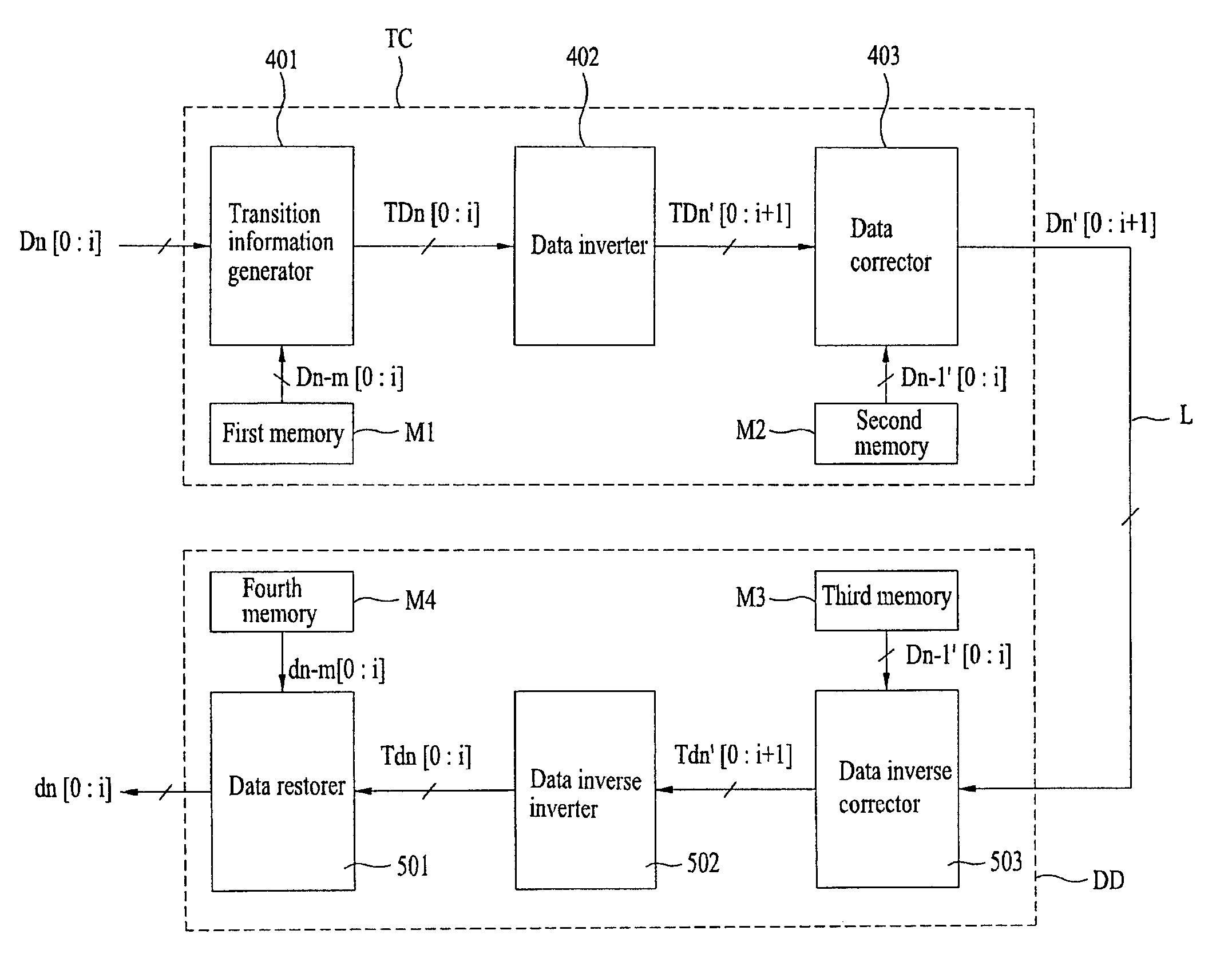
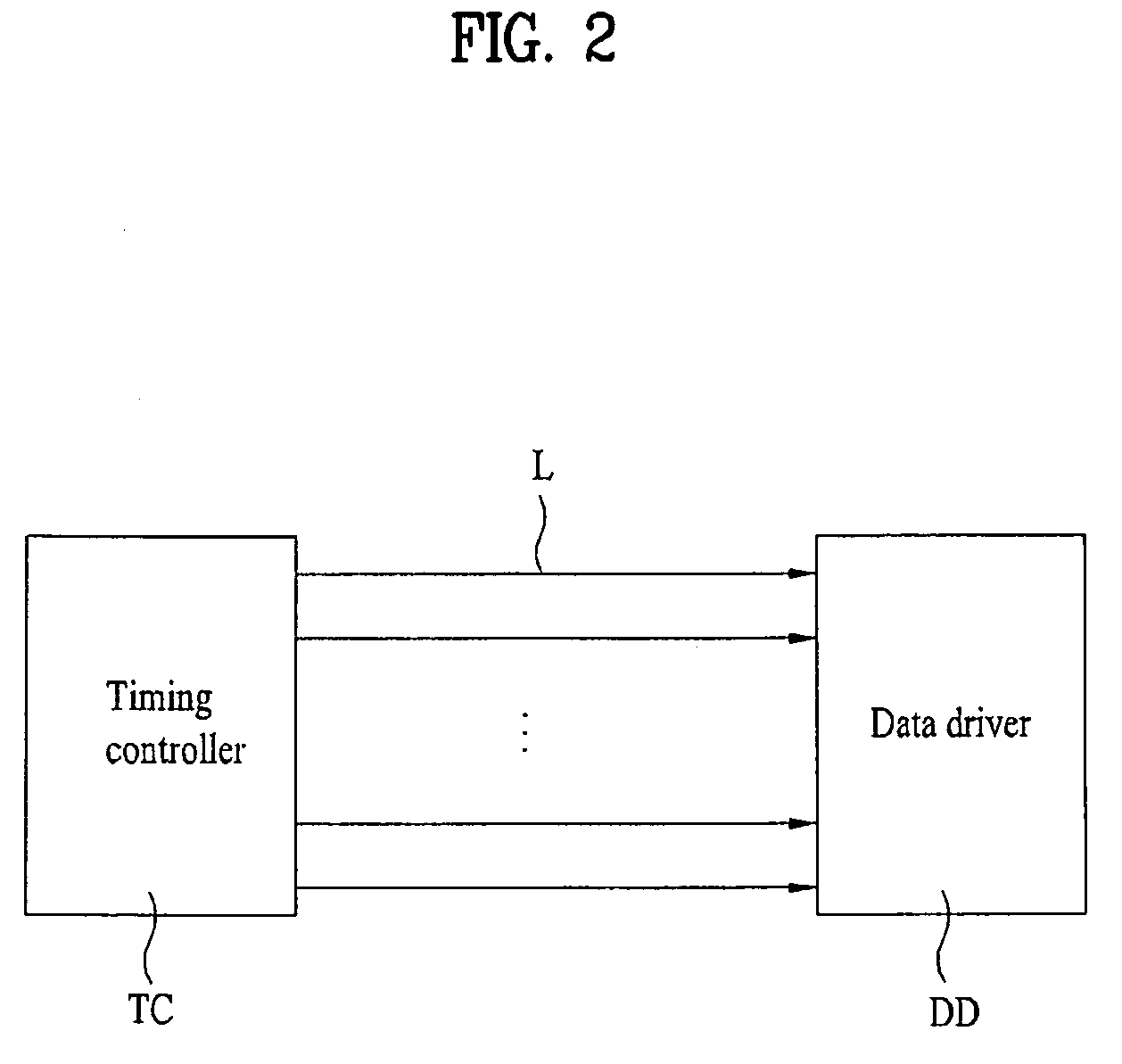
[0008]An object of the present invention is to provide a data transition minimization method and a data transition minimization circuit which can, based on a characteristic that little transition occurs between image data having the same color information, perform a comparison between those image data, generate transition information data based on the comparison result and modulate and restore image data to be currently outputted, based on the generated transition information data, so as to minimize a transition between image data which are transmitted from a timing controller to a data driver.

Problems solved by technology

However, in the case where the conventional method is applied to a display device which consecutively outputs data having different color information, little transition reduction effect can be seen.

Method used


Image

  • Method for minimizing data transition and circuit for minimizing data transition
  • Method for minimizing data transition and circuit for minimizing data transition
  • Method for minimizing data transition and circuit for minimizing data transition

Examples


Embodiment Construction

[0026]Reference will now be made in detail to the preferred embodiments of the invention, examples of which are illustrated in the accompanying drawings. Wherever possible, the same reference numbers will be used throughout the drawings to refer to the same or like parts.

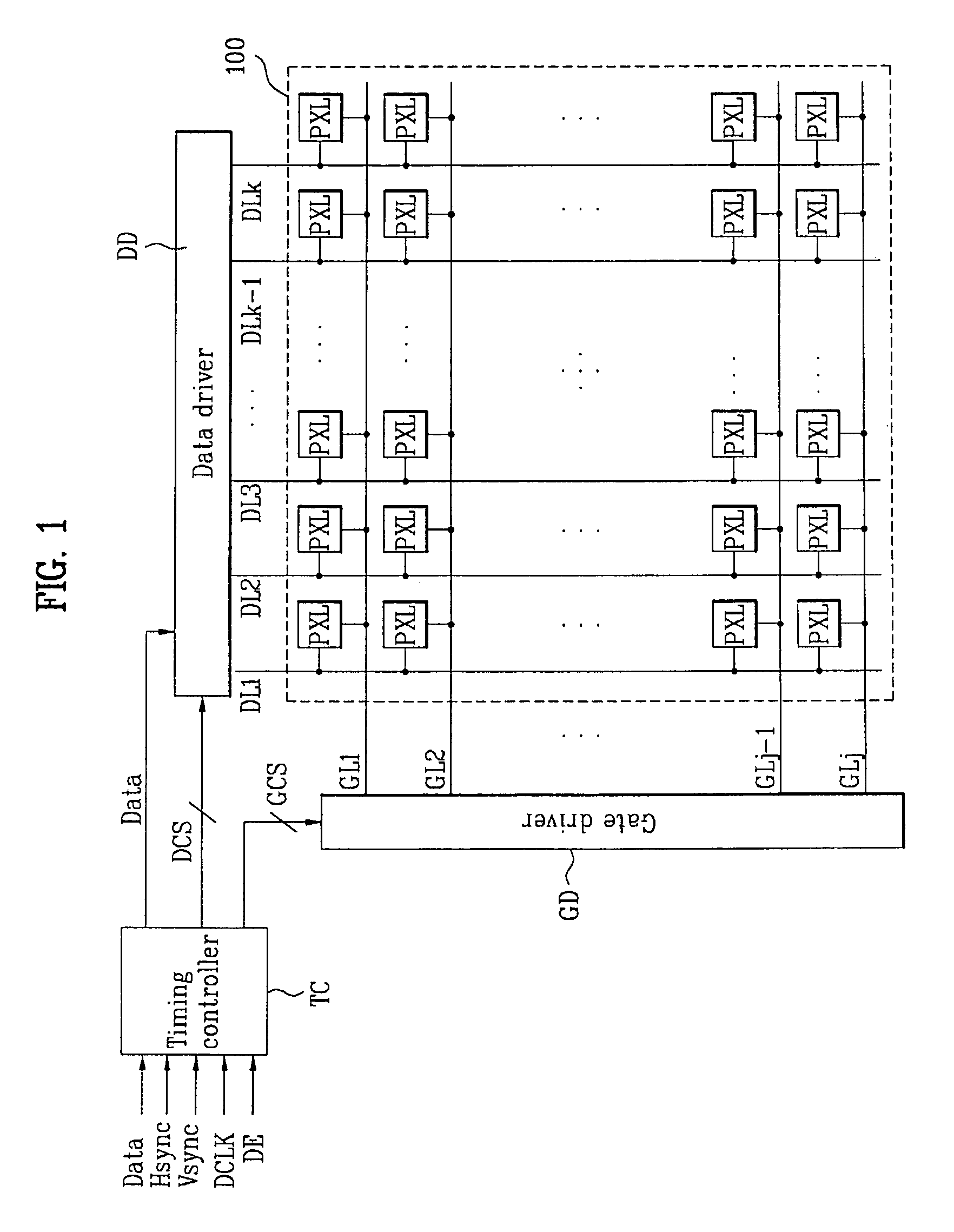
[0027]FIG. 1 is a schematic view of a liquid crystal display device according to an embodiment of the invention. The display device according to this embodiment comprises, as shown in FIG. 1, a liquid crystal panel 100 for displaying an image, a data driver DD for supplying data signals to the liquid crystal panel 100, a gate driver GD for supplying scan pulses to the liquid crystal panel 100, and a timing controller TC for generating various signals required for driving of the data driver DD and gate driver GD to control the data driver DD and gate driver GD.

[0028]The liquid crystal panel 100 includes a plurality of gate lines GL1 to GLj (where j is a natural number) arranged in one direction, a plurality of data l...


PUM


Abstract

A data transition minimization method includes exclusive-NORing inputted nth image data (where n is a natural number) and (n−m)th image data (where m is a natural number smaller than n) expressing the same color as that of the nth image data to generate transition information data; generating inversion data indicative of inversion information by inverting all bits included in the transition information data and adding a unit bit having the logic value ‘1’ to the inverted transition information data when the number of unit bits having a logic value ‘1’ in the transition information data is larger than the number of unit bits having a logic value ‘0’ in the transition information data, and adding a unit bit having the logic value ‘0’ to the transition information data when the number of unit bits having the logic value ‘1’ in the transition information data is equal to or smaller than the number of unit bits having the logic value ‘0’ in the transition information data; exclusive-NORing the transition information data with the inversion data added and corrected image data of (n−1)th image data to generate corrected image data of the nth image data, and supplying the generated corrected image data to a data driver through data transmission lines; and restoring the corrected image data supplied to the data driver to restored image data corresponding to the original nth image data.

Description

[0001]This application claims the benefit of the Korean Patent Application No. 10-2008-076214, filed on Aug. 4, 2008, which is hereby incorporated by reference as if fully set forth herein.BACKGROUND OF THE INVENTION[0002]1. Field of the Invention[0003]The present invention relates to a method for minimizing a data transition, and more particularly, to a data transition minimization method and a data transition minimization circuit which can minimize a transition between data having different color information.[0004]2. Discussion of the Related Art[0005]A conventional data transition minimization method is adapted to perform a comparison between two data which are outputted adjacent to each other in time and determine based on the comparison result whether to invert data to be currently outputted.[0006]However, in the case where the conventional method is applied to a display device which consecutively outputs data having different color information, little transition reduction effe...

Claims


Application Information

Patent Timeline
Patent Type & Authority Patents(United States)
IPC IPC(8): H03K19/21
CPCG09G3/2096G09G5/04G09G3/3648G09G2320/0276G09G5/393G09G3/3688G09G3/36G09G3/20G09G5/395G02F1/133
Inventor HONG, JIN CHEOLCHO, SOON DONGKANG, JEONG HOKIM, HYUN CHUL
Owner LG DISPLAY CO LTD
Learn More