Cyclone for separation of gas-liquid mixture, and a refrigerant accumulator containing this cyclone

a gas-liquid mixture and cyclone technology, which is applied in the direction of separation processes, vortex flow apparatus, lighting and heating apparatus, etc., can solve the problems of insufficient separation of r744 refrigerant, insufficient separation of components, and increased risk of damage to tangentially oriented inlet pipes, etc., to achieve the effect of reducing the efficiency of separating components and facilitating and cost-effective production

Active Publication Date: 2021-07-13
HANON SYST
View PDF19 Cites 0 Cited by
  • Summary
  • Abstract
  • Description
  • Claims
  • Application Information

AI Technical Summary

Benefits of technology

[0013]This cyclone design layout, i.e. a combination of a substantially axial mixture inlet with a helical vane, allows easier and cost-effective production as a single piece, for example by injection moulding. It is also more durable in subsequent assembly operations because there is no easy-to-destroy tangentially located inlet pipe. Replacing the tangential inlet of the mixture with the axial one does not reduce the efficiency of separating the components nor disturb other advantages of the known cyclones with radial inlet. The axial design also enables standardization of the cyclone for the heat transfer medium accumulator and the accumulator with the internal heat exchanger.

Problems solved by technology

These methods are not sufficient for separation of the R744 refrigerant.
From a production point of view, this type of cyclone must always be assembled from at least two or three components (the cyclone body, one or two bent pipes and the connecting piece) where the individual parts need to be joined or made by expensive and complex methods of plastic injection moulding (e.g. external gas injection moulding, GAD).
Furthermore, there is an increased risk of damage to the tangentially oriented inlet pipe during subsequent assembly operations.
There are cyclones with an axial or substantially axial inlet, but they do not contain a stationary vane to ensure rotation of the mixture and do not achieve sufficient separation of components or simplicity of construction.
In these cyclones, the mixture rotation is uneven, chaotic and does not achieve the desired quality of the outgoing medium.

Method used


Image

  • Cyclone for separation of gas-liquid mixture, and a refrigerant accumulator containing this cyclone
  • Cyclone for separation of gas-liquid mixture, and a refrigerant accumulator containing this cyclone
  • Cyclone for separation of gas-liquid mixture, and a refrigerant accumulator containing this cyclone

Examples


example 1

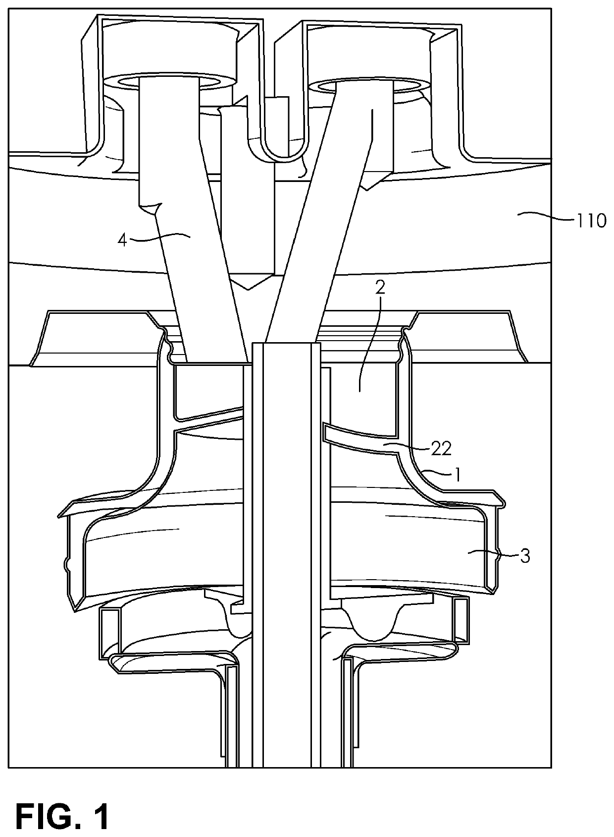
[0029]FIG. 1 shows a cyclone with an axial inlet and a lid 110 of the accumulator for separating the liquid and gaseous components from the inlet mixture of the liquid and gaseous components. The cyclone comprises a cyclone body 1 with one stationary vane 22 in the form of a helix for causing the rotational movement of the inlet mixture, a cylindrical inlet chamber 2, and an outlet chamber 3 which widens gradually from the outlet of the vane 22.

[0030]The cyclone is fitted on the lid 110 of the accumulator of heat exchange medium, and the inlet bore 4 in the lid 110 opens axially to the inlet chamber 2 substantially in the direction of the cyclone axis. The vane 22 in the form of a helix changes the direction of mixture flow so that the outlet at the end of the vane 22 transfers the mixture tangentially to the outlet chamber 3, in which part the mixture is already rotating and the separation of the liquid particles from the gas begins.

[0031]Cyclone is usually made of plastic by injec...

example 2

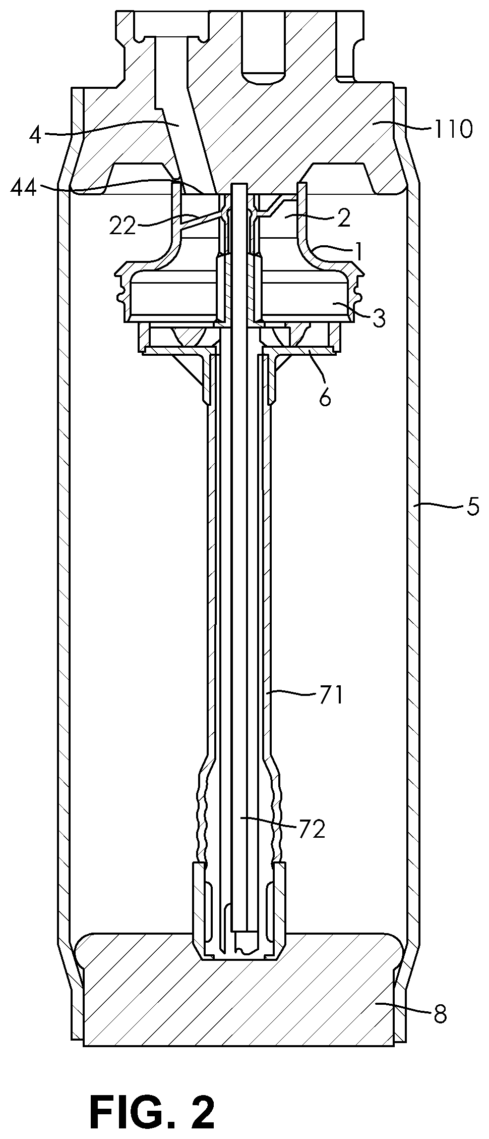
[0032]FIG. 2 shows a refrigerant accumulator that contains a vessel comprising a lid 110, a bottom 8, and a shell 5, wherein the lid 110 is coaxially connected to the cyclone of the present invention. In the lid, there is an inlet bore 4 passing through the lid substantially coaxially with the axis of the lid 110 and cyclone. The inlet bore 4 brings the mixture of liquid and gas through the axial inlet 44 to the inlet chamber 2 of the cyclone. An assembly of suction pipes 71, 72 passes between the lid 110 and the bottom 8 of the vessel to pipe away the gaseous refrigerant component. A deflector 6 is situated behind the cyclone outlet chamber 3, wherein the means for enriching the gaseous refrigerant with a pre-determined amount of oil are situated at the bottom 8 of the vessel (such means are disclosed, for example, in US 2015 / 0345844). The assembly of suction pipes 71, 72 to pipe away the gaseous refrigerant component comprises an outer suction pipe 71 for piping away the gaseous r...

example 3

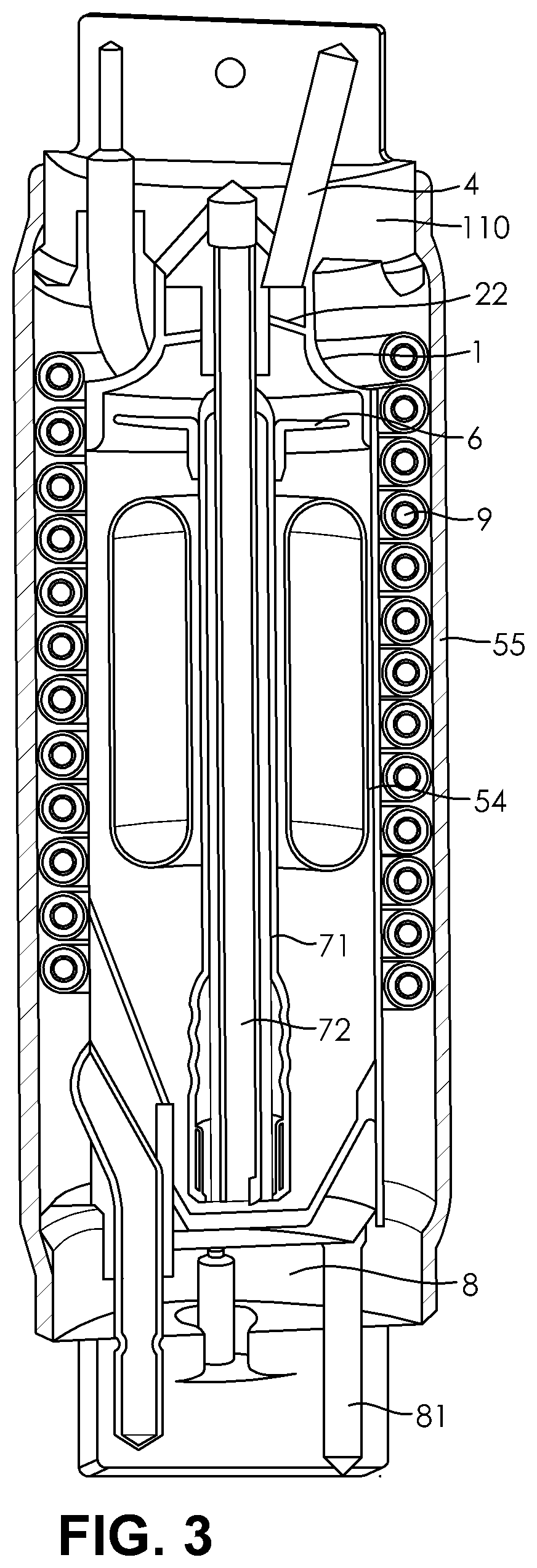
[0034]FIG. 3 shows an accumulator with integrated internal heat exchanger that contains an outer vessel comprising a lid 110, a bottom 8, and a shell 55, and an inner vessel 54, wherein the lid 110 is coaxially connected to the cyclone of the present invention. The gas-liquid mixture passes through the lid 110 through a bore 4 substantially coaxially with the axis of the lid 110 and cyclone and axially enters the inlet chamber of the cyclone body 1; between the vessel lid 110 and bottom 8, an assembly of suction pipes 71, 72 passes to pipe away the gaseous refrigerant component; a deflector 6 is located behind the cyclone outlet chamber in the inner vessel 54. In the bottom of the inner vessel 54 there are means for enriching the gaseous refrigerant with a pre-determined amount of oil. A heat exchanger in the form of a helically guided tube 9 is provided between the outer wall of the inner vessel 54 and the inner wall of the shell 55 of the outer vessel through which the refrigerant...


PUM

PropertyMeasurementUnit
shapeaaaaaaaaaa
diameteraaaaaaaaaa
pressureaaaaaaaaaa

Abstract

The present solution provides a cyclone for separation of gas-liquid mixtures, particularly suitable for a refrigerant accumulator or an accumulator with an internal heat exchanger in a vehicle air conditioning system using carbon dioxide as refrigerant, including an inlet of the gas-liquid mixture and a body of the cyclone with an inlet chamber, an outlet chamber, and at least one stationary vane in the form of a helix to ensure rotation of the mixture in the cyclone outlet chamber, where the gas-liquid mixture inlet is arranged substantially coaxially with the axis of the cyclone and opens directly into the inlet chamber of the cyclone body. The solution further provides a refrigerant accumulator and an accumulator with an integrated internal heat exchanger which includes the cyclone according to the invention.

Description

CROSS-REFERENCE TO RELATED PATENT APPLICATIONS[0001]This patent application claims the benefit of Czech Patent Application No. PV 2017-507 dated Aug. 31, 2017, the disclosure of which is hereby incorporated herein by reference in its entirety.FIELD OF THE INVENTION[0002]The present invention relates to a cyclone for separation of gas-liquid mixture, in particular for a refrigerant accumulator or an accumulator with an internal heat exchanger in a vehicle air conditioning system with carbon dioxide as refrigerant (technical grade R744).BACKGROUND OF THE INVENTION[0003]The refrigeration and air conditioning systems contain refrigerant accumulators in which the liquid component of the refrigerant is separated from the gaseous component of the refrigerant, and together with the liquid component, liquid oil is separated.[0004]The accumulator then provides for the addition of a precisely metered quantity of oil to the gaseous refrigerant that exits into other parts of the refrigeration or...

Claims


Application Information

Patent Timeline
Patent Type & Authority Patents(United States)
IPC IPC(8): B01D45/16F25B31/00F25B43/00F25B43/02
CPCB01D45/16F25B31/002F25B43/006F25B43/02F25B2309/06F25B2400/02F25B2400/03F25B9/008F25B2400/051F25B2400/054F25B2500/18B04C3/00B04C3/02B04C3/06B04C2003/006
Inventor ZAPLETAL, JIRI
Owner HANON SYST
Why Eureka
Try Eureka