Camshaft adjuster for an internal combustion engine having hydraulic medium guides

a technology of hydraulic medium and camshaft, which is applied in the direction of valve details, valve arrangements, valve drives, etc., can solve the problems of difficult to ensure the permanentity of the plastic part, the camshaft seat is fixed, and the oil foaming is not advantageous, so as to achieve easy and cost-effective production and simple and reliable supply of hydraulic medium.

Inactive Publication Date: 2006-02-28
DAIMLER AG
View PDF25 Cites 8 Cited by
  • Summary
  • Abstract
  • Description
  • Claims
  • Application Information

AI Technical Summary

Benefits of technology

[0009]At least one embodiment of the invention is designed for structuring a camshaft adjuster in interaction with a camshaft having an insert part, so that there is a simple and reliable supply of hydraulic medium to the camshaft adjuster and, in particular, its control device. In addition, at least one embodiment is designed so that this design allows easy and cost-effective production of the camshaft adjuster and hydraulic medium guide.
[0013]With this design, the transfer conduit of the hydraulic medium to be guided from the camshaft to the hydraulic medium guide channel located in the housing can be formed by providing grooves assigned to the individual channels in the housing and in the insert part, or by way of an appropriately configured transfer unit between the housing and the camshaft. This transfer unit can be arranged on the outer mantling of the camshaft. With this design, based on the way in which hydraulic medium guides are configured, by means of an insert part inserted into the camshaft, there is no machining required for the camshaft or components adjacent to the camshaft, with regard to making axially running hydraulic medium channels. Thus, the machining effort in this regard is completely eliminated. The formation of axial channels that are not structured to be coaxial results in the advantage of optimal positioning of the channels with regard to the hydraulic medium channel function, as well as the connection of the transfer interfaces with the control valve as well as with the camshaft adjuster at the camshaft.
[0014]Furthermore, for a simple representation of the insert part, for example, by means of plastic injection molding or light metal die-casting, the formation of non-coaxial channels that are aligned at least approximately in the camshaft axis, with radial connection channels, is advantageous, since the mold die requires only individual lateral slides or a simple divided mold die.
[0018]Furthermore, the operational reliability of the camshaft adjustment increases, since possible causes of failure are eliminated with the elimination of the screw connections. Furthermore, a cost reduction is also achieved in that the interfaces for joining become simpler.

Problems solved by technology

The ribbed insert shown has the disadvantage that the stream of oil must flow around many edges, which are disadvantageous in terms of flow technology, and this results in disadvantageous oil foaming, particularly due to the rotating camshaft.
In addition, the proposed embodiment shown as a plastic part does not ensure any permanent, fixed seat in the camshaft, because of creep at the engine operating temperature.
Furthermore, the ribs shown, in combination with the ring grooves, cause a complicated die embodiment in an injection-molding die.
Accordingly, there is a relatively high level of machining effort for channels in the camshaft that carry hydraulic medium, i.e. in components adjacent to the camshaft.
However, this has the disadvantage of a very limited channel design, which can only be used with certain restrictions for supplying hydraulic medium to a camshaft adjuster.
This design has the disadvantage that the insert part must have a high level of dimensional accuracy, if independent channels are formed in adjacent grooves, in order to provide a secure seal.
This is particularly difficult to accomplish with the specific embodiment disclosed, which has a formed sheet-metal part.

Method used


Image

  • Camshaft adjuster for an internal combustion engine having hydraulic medium guides
  • Camshaft adjuster for an internal combustion engine having hydraulic medium guides
  • Camshaft adjuster for an internal combustion engine having hydraulic medium guides

Examples


fourth embodiment

[0045]FIG. 4 shows camshaft adjuster 1 with an insert part 4. Insert part 4 is inserted, with a positive lock, into the hollow camshaft 2, which has a wave-shaped region 39 at its end, wherein this region is arranged in the region of an additional camshaft bearing 40. Since insert part 4 is inserted into camshaft 2 with a positive lock, it therefore also forms a corresponding wave-shaped region 41. The open end of hollow camshaft 2, which faces lid 9, (See FIG. 1) is closed off with a closure lid 42 that is arranged within insert part 4. Camshaft adjuster 1 has a locking mechanism formed from a bolt 43 and a pressure spring, not shown here, which can be activated hydraulically, and provides a rigid connection between inner body 12 and drive wheel 10 via an axial movement of bolt 43. This connection can be released by applying hydraulic medium to camshaft adjuster 1, in a targeted manner, and an adjustment is released.

[0046]To supply hydraulic medium to the camshaft adjuster, as show...

fifth embodiment

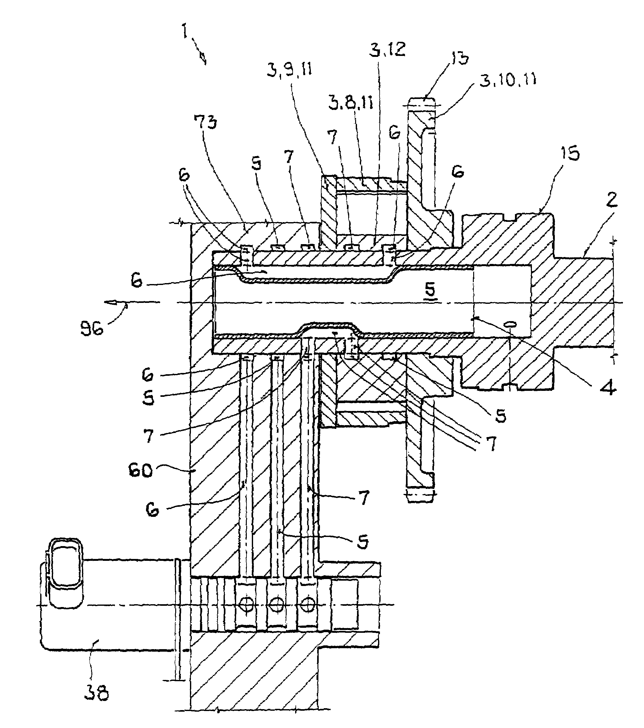
[0049]FIG. 5 shows a camshaft adjuster 1 wherein insert part 4 is structured as a combination molded part, the body of which consists at least predominantly of plastic or aluminum. Insert part 4 contains hydraulic medium guides 5, 6 and 7, at least in part, or forms them together with camshaft 2. Furthermore, insert part 4 has support elements 59 such as support rings or support ring segments, for example, which stand in mechanical contact with the inside wall of camshaft 2 in the installed state of insert part 4. Camshaft adjuster 1 includes hydraulic control valve 38 that is arranged outside camshaft 2, in housing 60 of the internal combustion engine. Camshaft adjuster 1 has the three hydraulic medium circuits 5, 6, and 7, which can be controlled via control valve 38, whereby part of the hydraulic medium circuits 5, 6, and 7 are formed via non-coaxial channels 61, and 62 in insert part 4.

[0050]Control valve 38 is supplied with hydraulic medium via a first hydraulic medium circuit ...

seventh embodiment

[0053]FIG. 7 shows a camshaft adjuster 1 with a one-piece insert part 4 that has cross-sections that change in the axial longitudinal direction 96, and with the hydraulic medium circuits 5, 6 and 7. Alternatively, it would be possible that insert part 4 has non-coaxial channels, for example according to FIG. 6, and / or contours with uniform and / or variable cross-sections over axial length 96, for example as shown in FIG. 7, or forms them together with camshaft 2.


PUM


Abstract

A camshaft adjuster for an internal combustion engine having hydraulic medium guides. The adjuster can include a setting unit that can be controlled by a control unit using these guides in the adjuster, wherein the setting unit is for adjusting an angle of a camshaft. This setting unit has an inner body coupled to the camshaft so as to rotate with it, and an outer body that is mounted to rotate relative to the camshaft via a drive connection which runs from a crankshaft to the camshaft. The camshaft has at least one insert part permanently inserted camshaft wherein these two components together form at least one hydraulic medium guide at least in partial regions over its axial length. This design is to create a camshaft adjuster which is in interaction with a camshaft having an insert part so that there is a simple and reliable supply of hydraulic medium to the camshaft adjuster and in particular to its control device.

Description

CROSS REFERENCE TO RELATED APPLICATIONS[0001]This application hereby claims priority from German Application Serial No. 103 46 446.8 filed on Oct. 7, 2003, wherein priority is claimed under 35 U.S.C. §119.BACKGROUND OF THE INVENTION[0002]The invention relates to a camshaft adjuster for an internal combustion engine having hydraulic medium guides.[0003]To reduce fuel consumption and the emission of untreated gases, as well as to increase power and torque, diesel engines are generally fitted with camshaft adjusters. These adjusters change the phase position of the camshaft relative to the crankshaft. Currently, hydraulic vane cell adjusters having working chambers are used, in most instances. The adjustment is made via the controlled entry of oil into the chambers of the vane cells, from the engine circuit, via a control valve. The control valve is moved by means of an electromagnetic device.[0004]A camshaft adjuster of this type, for an internal combustion engine having hydraulic med...

Claims


Application Information

Patent Timeline
Patent Type & Authority Patents(United States)
IPC IPC(8): F01L1/34F01L1/047F01L1/344
CPCF01L1/022F01L1/047F01L1/3442F01L1/024F01L1/026F01L2103/00F01L2001/34426F01L2001/3443F01L2001/34433F01L2101/00F01L2001/0475F01L2301/00F01L2303/00
Inventor BOLZ, GERALDHASER, CHRISTIANLEHMANN, KAISCHMIDT, TIMO
Owner DAIMLER AG
Why Eureka
Try Eureka