Resin-molded capacitor and power conversion device
a technology of a power conversion device and a resin-molded capacitor, which is applied in the direction of stacked capacitors, capacitor collector combinations, fixed capacitor details, etc., can solve the problems of generating noise accompanying the vibration, the capacitor element cannot be restricted, etc., and achieves efficient dissipation
- Summary
- Abstract
- Description
- Claims
- Application Information
AI Technical Summary
Benefits of technology
Problems solved by technology
Method used
Image
Examples
first embodiment
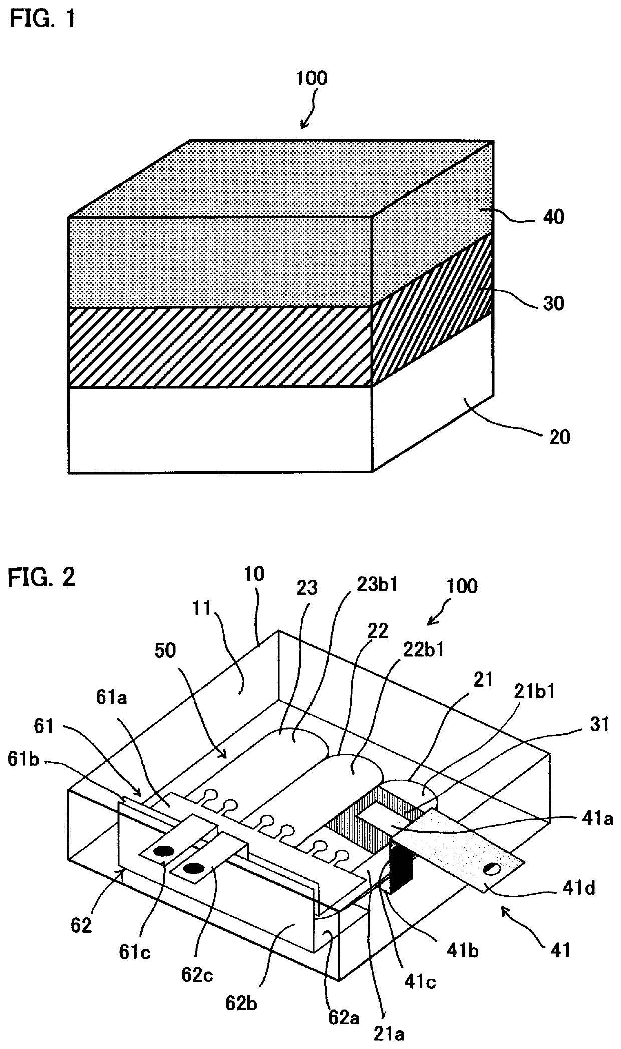
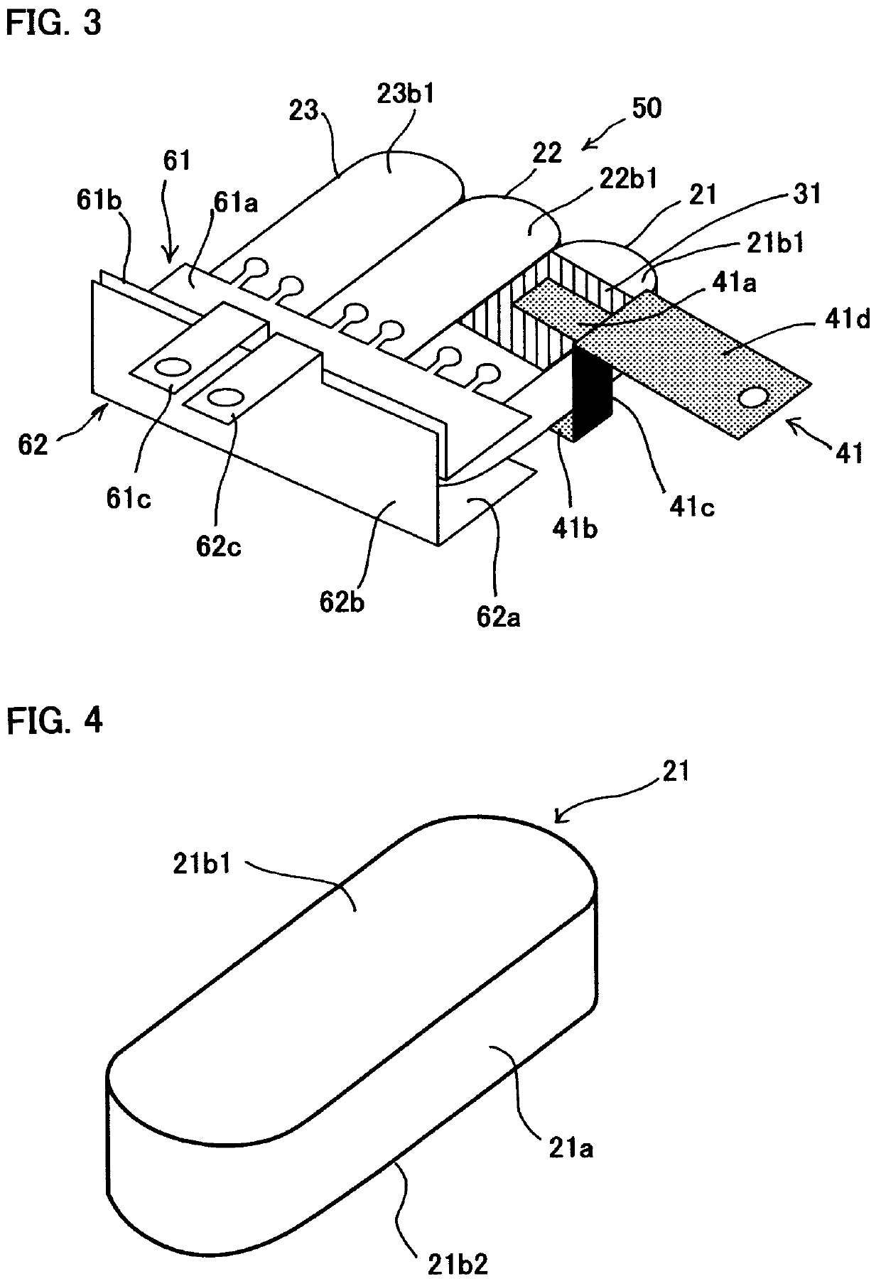
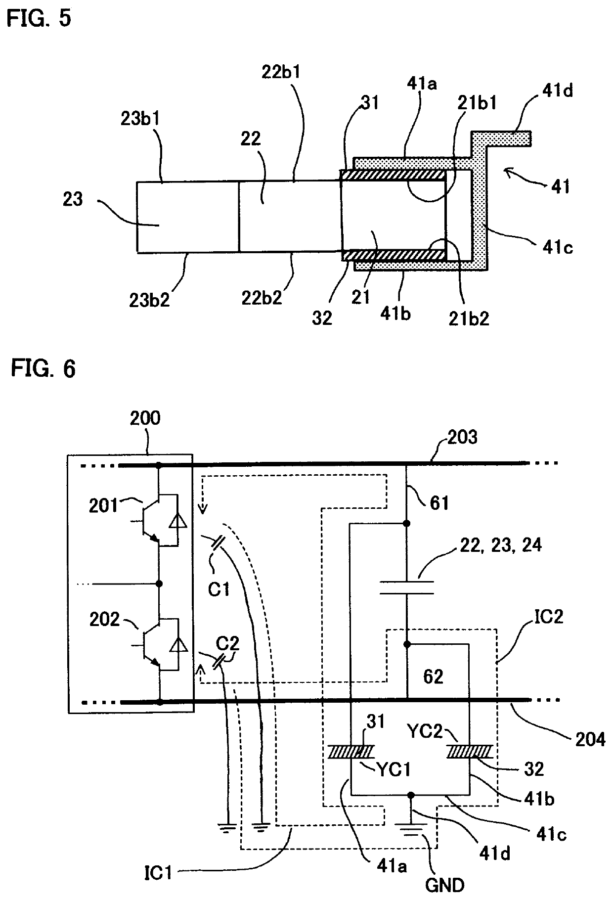
[0035]Next, a resin-molded capacitor according to a first embodiment will be described. FIG. 2 is an illustration of the resin-molded capacitor according to the first embodiment, FIG. 3 is an illustration showing a configuration of a capacitor main body of the resin-molded capacitor according to the first embodiment, FIG. 4 is a schematic view showing a configuration of a capacitor element used in the resin-molded capacitor according to the first embodiment, and FIG. 5 is a schematic sectional view of the resin-molded capacitor according to the first embodiment. In FIGS. 2 and 3, the resin-molded capacitor 100, which is formed into a module, includes a case 10 configured of an insulating member such as a resin, a molding resin 11 formed of, for example, an epoxy resin packed into an interior of the case 10, and a capacitor main body 50 insert molded in the molding resin 11.
[0036]The capacitor main body 50 includes a first capacitor element 21, a second capacitor element 22, and a th...
second embodiment
[0057]Next, a resin-molded capacitor according to a second embodiment will be described. FIG. 7 is an illustration of the resin-molded capacitor according to the second embodiment, and schematically shows only a portion differing from the resin-molded capacitor according to the first embodiment. In FIG. 7, the first insulating member 31 is joined to a surface of the first capacitor electrode 21b1 of the first capacitor element 21. A second insulating member (not shown) is joined to a surface of the second capacitor electrode 21b2 of the first capacitor element 21.
[0058]A first electrically conductive member 42 includes a first region 42a joined to a surface of the first insulating member 31, a second region 42b standing bent at a predetermined angle (for example, 90 degrees) from the first region 42a, and a first fastening terminal 42c bent at a predetermined angle (for example, 90 degrees) to a non-capacitor element side from the second region 42b. The first electrically conductive...
third embodiment
[0065]Next, a resin-molded capacitor according to a third embodiment will be described. FIG. 8 is an illustration showing a configuration of a capacitor main body of the resin-molded capacitor according to the third embodiment. In FIG. 8, a first insulating member 33 is configured of a material having a modulus of elasticity higher than a modulus of elasticity of a first electrically conductive member 44 to be described hereafter, and having an insulating property, and is joined to the winding face 21a of the first capacitor element 21. In the same way, a second insulating member (not shown) is configured of a material having a modulus of elasticity higher than a modulus of elasticity of a second electrically conductive member 45 to be described hereafter, and having an insulating property, and is joined to a winding face of the third capacitor element 23.
[0066]The first electrically conductive member 44, which is configured of metal, includes a first region 44a joined to a surface ...
PUM
| Property | Measurement | Unit |
|---|---|---|
| angle | aaaaa | aaaaa |
| thickness | aaaaa | aaaaa |
| electrically conductive | aaaaa | aaaaa |
Abstract
Description
Claims
Application Information
 - R&D
- Intellectual Property
- Life Sciences
- Materials
- Tech Scout
- Unparalleled Data Quality
- Higher Quality Content
- 60% Fewer Hallucinations
Browse by: Latest US Patents, China's latest patents, Technical Efficacy Thesaurus, Application Domain, Technology Topic, Popular Technical Reports.
© 2025 PatSnap. All rights reserved.Legal|Privacy policy|Modern Slavery Act Transparency Statement|Sitemap|About US| Contact US: help@patsnap.com


