
Radiation imaging apparatus

a technology of radiation imaging and apparatus, applied in the field of radiation imaging apparatus, can solve the problems of reducing the accuracy of radiation imaging, difficult to obtain, and difficulty in obtaining radiation images, and achieve the effect of reducing the variation in tim

Active Publication Date: 2021-06-29
CANON KK
View PDF61 Cites 1 Cited by
  • Summary
  • Abstract
  • Description
  • Claims
  • Application Information

AI Technical Summary

Benefits of technology

The patent talks about a way to make sure that signals can be measured accurately, right after they start being exposed to radiation. This helps to get consistent results and reduces the time it takes to get the measurements.

Problems solved by technology

It is therefore difficult to obtain, by the energy subtraction method, a radiation image of an object such as a heart that moves fast.
This can cause a decrease in accuracy of energy subtraction.

Method used


Image

  • Radiation imaging apparatus
  • Radiation imaging apparatus
  • Radiation imaging apparatus

Examples


Embodiment Construction

[0022]Exemplary embodiments of the present invention will be explained below with reference to the accompanying drawings.

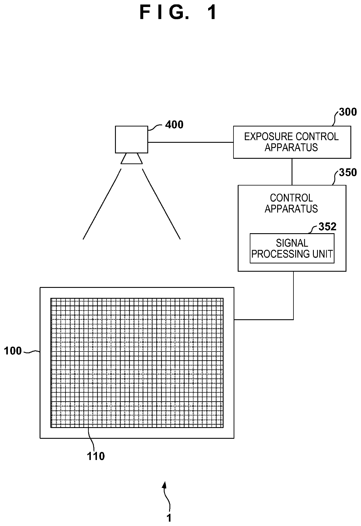
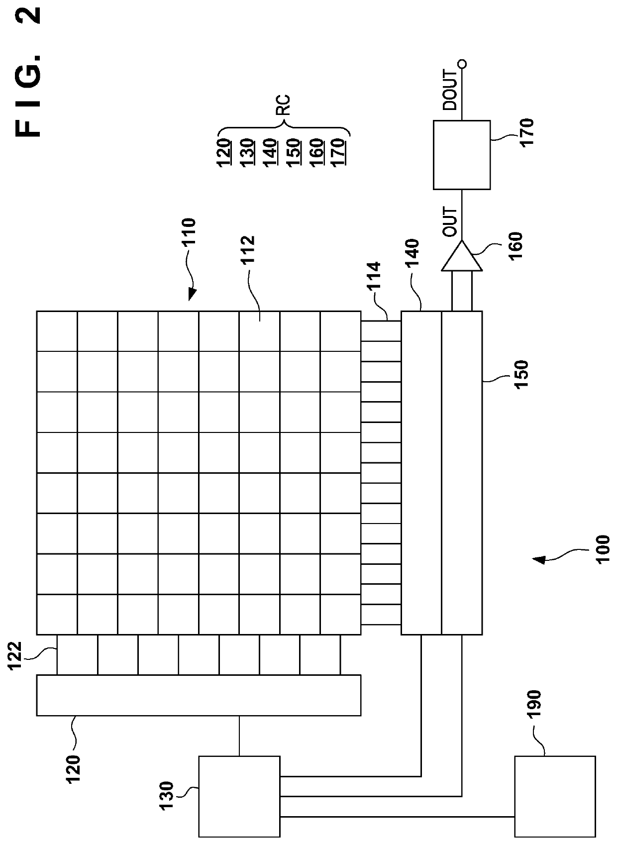
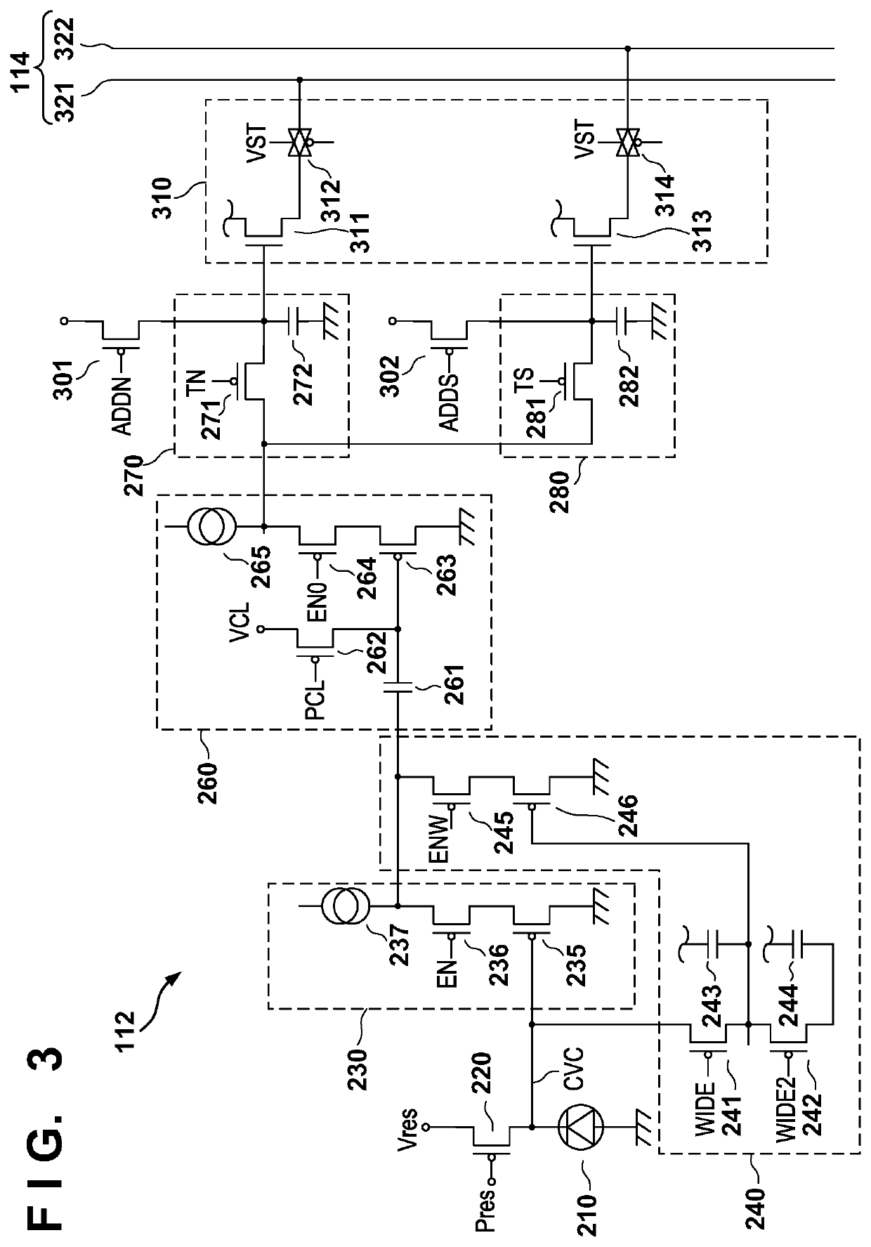
[0023]FIG. 1 shows the arrangement of a radiation imaging apparatus 1 according to the first embodiment of the present invention. The radiation imaging apparatus 1 can include an imaging unit 100 including a pixel array 110 including a plurality of pixels and a signal processing unit 352 that processes a signal from the imaging unit 100. The imaging unit 100 can have, for example, a panel shape. As exemplified in FIG. 1, the signal processing unit 352 may be arranged as part of a control apparatus 350, incorporated in the same housing as the imaging unit 100, or incorporated in a housing different from that of the imaging unit 100 and the control apparatus 350. The radiation imaging apparatus 1 is an apparatus for obtaining a radiation image by an energy subtraction method. The energy subtraction method is a method of obtaining new radiation images (for example, a...


PUM


Abstract

Radiation imaging apparatus includes pixel array having pixels, readout circuit for reading signals from the pixel array, and detector for detecting, based on radiation emitted from radiation source or information provided from the radiation source, start of radiation irradiation by the radiation source, and controller for determining timing of each of operations of sample and hold in each of the pixels each time the start of radiation irradiation is detected by the detector. The timing of at least one operation of the operations is timing in radiation irradiation period, and each of the pixels includes convertor for converting radiation into electrical signal, and sample and hold circuit for sample-holding the signal from the conversion element over plural times in accordance with the timing of each of the operations determined by the controller.

Description

CROSS-REFERENCE TO RELATED APPLICATIONS[0001]This application is a Continuation of International Patent Application No. PCT / JP2018 / 027533, filed Jul. 23, 2018, which claims the benefit of Japanese Patent Application No. 2017-146801, filed Jul. 28, 2017, both of which are hereby incorporated by reference herein in their entirety.BACKGROUND OF THE INVENTIONField of the Invention[0002]The present invention relates to a radiation imaging apparatus.Background Art[0003]There is an energy subtraction method as an imaging method that applies a radiation imaging apparatus. The energy subtraction method is a method of obtaining new images (for example, a bone image and a soft tissue image) by processing a plurality of images obtained by capturing an object a plurality of times while changing energy of radiation to irradiate the object. A time interval during which a plurality of radiation images are captured is, for example, several seconds or more in a radiation imaging apparatus to capture ...

Claims


Application Information

Patent Timeline
Patent Type & Authority Patents(United States)
IPC IPC(8): H01L27/146G01T1/17G01T1/29
CPCG01T1/17G01T1/2928H01L27/14663H04N5/3205A61B6/54A61B6/4233A61B6/482A61B6/5264H04N25/771H04N25/78H04N25/40H04N25/77
Inventor TERUI, KOSUKEIWASHITA, ATSUSHITSUKUDA, AKIRATORII, SOTA
Owner CANON KK
Learn More