Wheel space detecting device

a detection device and space technology, applied in measurement devices, mechanical measuring arrangements, instruments, etc., can solve the problems of poor detection effect, high labor intensity, low efficiency, etc., and achieve stable detection performance, high positioning precision, and simple structure

Active Publication Date: 2021-06-29
CITIC DICASTAL
View PDF17 Cites 3 Cited by
  • Summary
  • Abstract
  • Description
  • Claims
  • Application Information

AI Technical Summary

Benefits of technology

[0006]The first servo motor, the pedestal and the shaft sleeve are mounted on the frame through the bottom plate; the output shaft of the first servo motor is connected to the base through the adapter shaft; the radial bearing is connected to the shaft sleeve and the base respectively and enclosed in the shaft sleeve and the base by the lower end cap; the pressure bearing is mounted on the pedestal and connected to the base. Through the pressure bearing and the radial bearing, the first servo motor may drive the base to rotate around the axis of the radial bearing with high precision.
[0007]The guide rail, the clamping cylinder, the first linear guide rails and the second sleeve are mounted on the base; the second bearing and the shaft are enclosed in the second sleeve through the second end cap, and the gear is mounted at the upper end of the shaft. Left and right clamping execution structures are symmetrically mounted on the base, and one of the first sliding seat frames is connected to one of the first linear guide rails through one of the first guide rail sliding seats; one side of the rack is fixed on one of the first sliding seat frames, and the other side is engaged with the gear; one of the first sleeves is fixed on one of the first sliding seat frames and enclosed inside one of the first sleeves through one of the first end caps, one of the first bearings and one of the first rotating shafts, and the clamping wheels are mounted at the upper end of the rotating shafts; each of the left and right clamping execution structures is provided with two clamping wheels distributed symmetrically; the output shaft of the clamping cylinder is connected to the left first sliding seat frame. Through the synchronization mechanism of the racks and the gear, the clamping cylinder may drive the left-right symmetric clamping execution structures to move synchronously horizontally along the first linear guide rails to achieve high-precision clamping and loosening of a wheel.
[0012]The present application may meet the needs of wheel brake space detection, has the characteristics of simple structure, stable detection performance, high positioning precision, simple operation and the like, and therefore is very suitable for automatic batch production.

Problems solved by technology

Such a detection method has the problems of low efficiency, high labor intensity and poor detection effect.

Method used


Image

  • Wheel space detecting device

Examples


Embodiment Construction

[0015]The details and working conditions of the specific device according to the present application will be described in detail below in combination with the drawing.

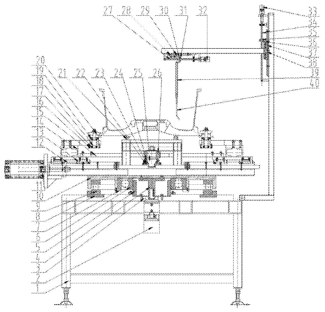
[0016]As shown in FIG. 1, a wheel space detecting device according to the present application consists of a frame 1, a first servo motor 2, a bottom plate 3, an adapter shaft 4, a shaft sleeve 5, a radial bearing 6, a lower end cap 7, a pedestal 8, a pressure bearing 9, a base 10, a clamping cylinder 11, first linear guide rails 12, first guide rail sliding seats 13, first sliding seat frames 14, racks 15, first sleeves 16, first bearings 17, rotating shafts 18, first end caps 19, clamping wheels 20, a guide rail 21, a second sleeve 22, a second bearing 23, a second end cap 24, a shaft 25, gears 26, a first lead screw 27, a second guide rail sliding seat 28, a second linear guide rail 29, a second sliding frame 30, a first lead screw nut 31, a second servo motor 32, a third servo motor 33, a second lead screw 34, a sec...


PUM


Abstract

The present application discloses a wheel space detecting device, comprising a frame, a first servo motor, a bottom plate, an adapter shaft, a shaft sleeve, a radial bearing, a lower end cap, a pedestal, a pressure bearing, a base, a clamping cylinder, first linear guide rails, first guide rail sliding seats, first sliding seat frames, racks, first sleeves, first bearings, rotating shafts, first end caps, clamping wheels, a guide rail, and so on. The present invention can meet the needs of wheel brake space detection, has the characteristics of simple structure, stable detection performance, high positioning precision, simple operation and the like, and therefore is very suitable for automatic batch production.

Description

CROSS-REFERENCE TO RELATED APPLICATIONS[0001]This application claims priority to Chinese Patent Application No. 201811298010.2, filed on Nov. 2, 2018, which is hereby incorporated by reference in its entirety.TECHNICAL FIELD[0002]The present application relates to a wheel space detecting device, specifically to a device for automatically detecting a wheel brake space after the completion of wheel machining process.BACKGROUND ART[0003]As safety parts and exterior parts of a vehicle, wheels need to be assembled on the vehicle. At the same time, the wheel back cavity needs to be equipped with a brake drum, a speed sensor, a balance block and other devices. Therefore, the brake space of the wheel back cavity needs to be comprehensively compatible with the spatial positions of the brake drum, the speed sensor and the balance block. Enterprises usually detect whether the brake space is qualified by adopting a matching gauge such as a detection plate. Such a detection method has the proble...

Claims


Application Information

Patent Timeline
Patent Type & Authority Patents(United States)
IPC IPC(8): G01B5/00
CPCG01B5/0025G01B5/0004G01B21/00G01B21/16G01M17/013
Inventor XU, ZUOXIONG, GUOYUANLIU, WEIDONGZHANG, NAYUE, LIANGJIANWANG, YINGFENG
Owner CITIC DICASTAL
Why Eureka
Try Eureka