Terminal fitting
a terminal fitting and fitting technology, applied in the direction of coupling contact members, coupling device connections, connections effected by permanent deformation, etc., can solve the problems of limiting improper insertion and preventing insertion of terminal fittings
- Summary
- Abstract
- Description
- Claims
- Application Information
AI Technical Summary
Benefits of technology
Problems solved by technology
Method used
Image
Examples
first embodiment
[0022](Connector Housing 1)
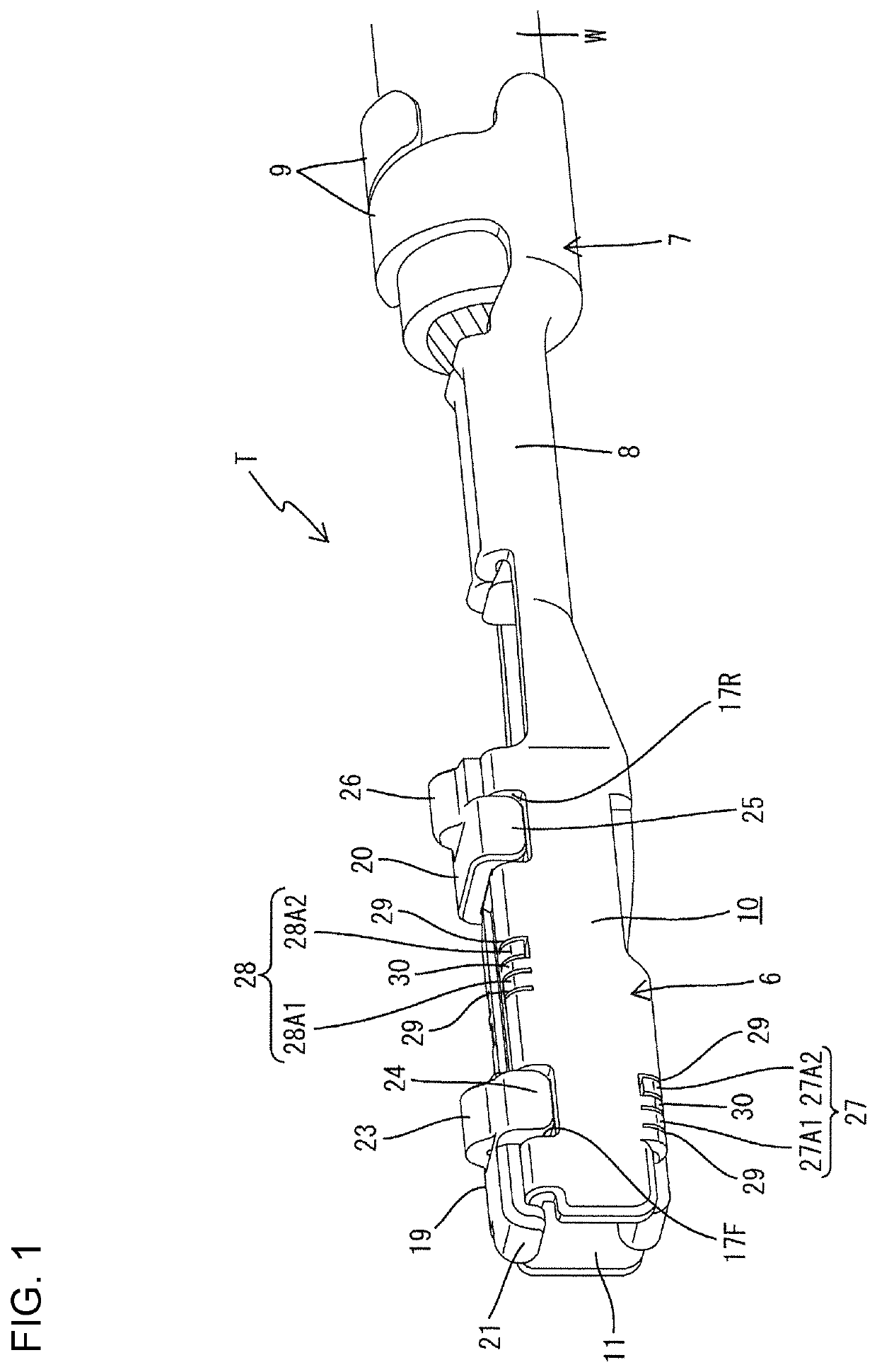
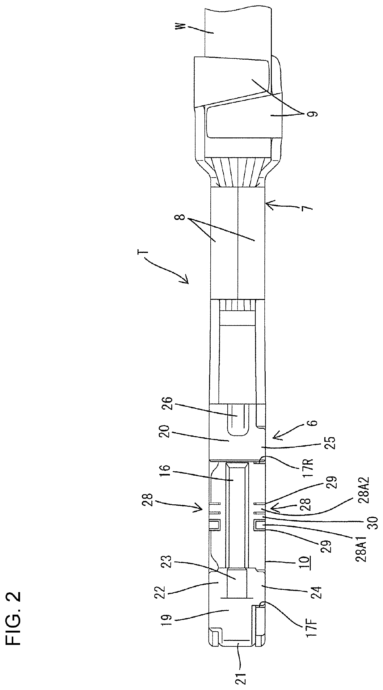
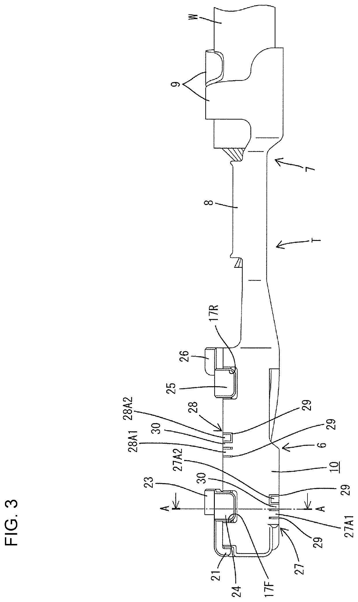
[0023]FIGS. 1 to 8 show the first embodiment of the invention. First, a connector housing 1 for accommodating terminal fittings T according to the first embodiment is described. As shown in FIG. 6, the connector housing 1 is composed of a terminal accommodating portion 2 for accommodating the terminal fittings T and a receptacle 3 surrounding the terminal accommodating portion 2. Cavities 4 for accommodating the terminal fittings T are provided in upper and lower stages in the terminal accommodating portion 2.
[0024]Each terminal fitting T is inserted into each cavity 4 from behind. As shown in FIGS. 7 and 8, each cavity 4 has a substantially rectangular cross-section long in a vertical direction and short in a width direction.
[0025]Each cavity 4 has a guide groove 5 recessed substantially over the entire length from an entrance of the cavity 4 and allows the insertion of stabilizers 23, 26 to be described later while guiding the stabilizers 23, 26 when the...
second embodiment
[0050]FIG. 9 shows the second embodiment of the invention. Although the resilient pieces 27A1, 27A2, 28A1 and 28A2 are curved in conformity with curved shapes of the corner parts of the rectangular tube 10 in the first embodiment, resilient pieces extend straight in vertical and lateral directions from a wall surface constituting a rectangular tube 10 in oblique insertion restricting portions 31, 32 in the second embodiment. As in the first embodiment, the periphery of each resilient piece 31A1, 31A2, 32A1, 32A2 is a cantilever by forming a slit 29, and is deflectable and deformable, although only to a slight extent. Further, unlike the first embodiment, the resilient pieces 31A1, 31A2, 32A1 and 32A are formed such that tip sides partially project from the periphery of the rectangular tube 10.
[0051]The other configuration is similar to the first embodiment. Hence, similar functions and effects can be achieved.
[0052]The invention is not limited to the above described and illustrated ...
PUM
 Abstract
Description
Claims
Application Information
 - R&D
- Intellectual Property
- Life Sciences
- Materials
- Tech Scout
- Unparalleled Data Quality
- Higher Quality Content
- 60% Fewer Hallucinations
Browse by: Latest US Patents, China's latest patents, Technical Efficacy Thesaurus, Application Domain, Technology Topic, Popular Technical Reports.
© 2025 PatSnap. All rights reserved.Legal|Privacy policy|Modern Slavery Act Transparency Statement|Sitemap|About US| Contact US: help@patsnap.com


