
Manual device for applying a coating to a support by means of tape

a man-made device and tape technology, applied in the direction of transportation and packaging, thin material handling, article delivery, etc., can solve the problem that the coating carried by the tape is often damaged before its application, and achieve the effect of reducing the stresses of the tap

Active Publication Date: 2021-05-04
SOC DITE SOC BIC
View PDF6 Cites 0 Cited by
  • Summary
  • Abstract
  • Description
  • Claims
  • Application Information

AI Technical Summary

Benefits of technology

[0014]Such a configuration makes it possible to minimize the stresses to which the tape between the windings and tip is subjected, which preserves the integrity of the coating before application. Furthermore, this configuration does away with elements for guiding and aligning the tape with the applicator tip such as those found in state of the art manual devices; this avoids imposing frictional stress on the tape and affords the user a more free-flowing application. The travel of the tape is thus more natural, including at the applicator tip. This also frees up space inside the manual device compared to state of the art manual devices. It is thus possible to provide a larger quantity of tape, which gives the manual device a longer life.
[0017]This minimizes the stresses undergone by the tape, while guaranteeing that a minimum amount of space is occupied within the manual device, which maximizes the quantity of tape that it can contain.
[0023]Such offsetting of the bearings avoids interference between the two windings, which makes it possible to adjust the position of the bearings in relation to the median plane, for example by bringing them closer to the median plane, so as to ensure an even better alignment in the longitudinal direction of the tape with the applicator tip, whatever the state of the windings. This makes it possible to further reduce the stresses undergone by the tape.
[0025]By choosing the first bearing as the bearing furthest from the applicator tip, the pitch of the twist undergone by the tape coming off the first winding, that is to say the portion of tape having the coating, is minimized. This thus minimizes the stresses undergone by the portion of tape with the coating, which ensures better integrity of the tape. Clearly, it will be understood that the pitch of the twist undergone by the tape that travels from the application edge to the second winding is greater, but remains acceptable, thanks to the alignment in the longitudinal direction of the second winding with the tip, in order to prevent the formation of folds in the tape. Moreover, as the coating has already been deposited, this portion of tape can undergo a greater pitch of twist without risk for the coating.
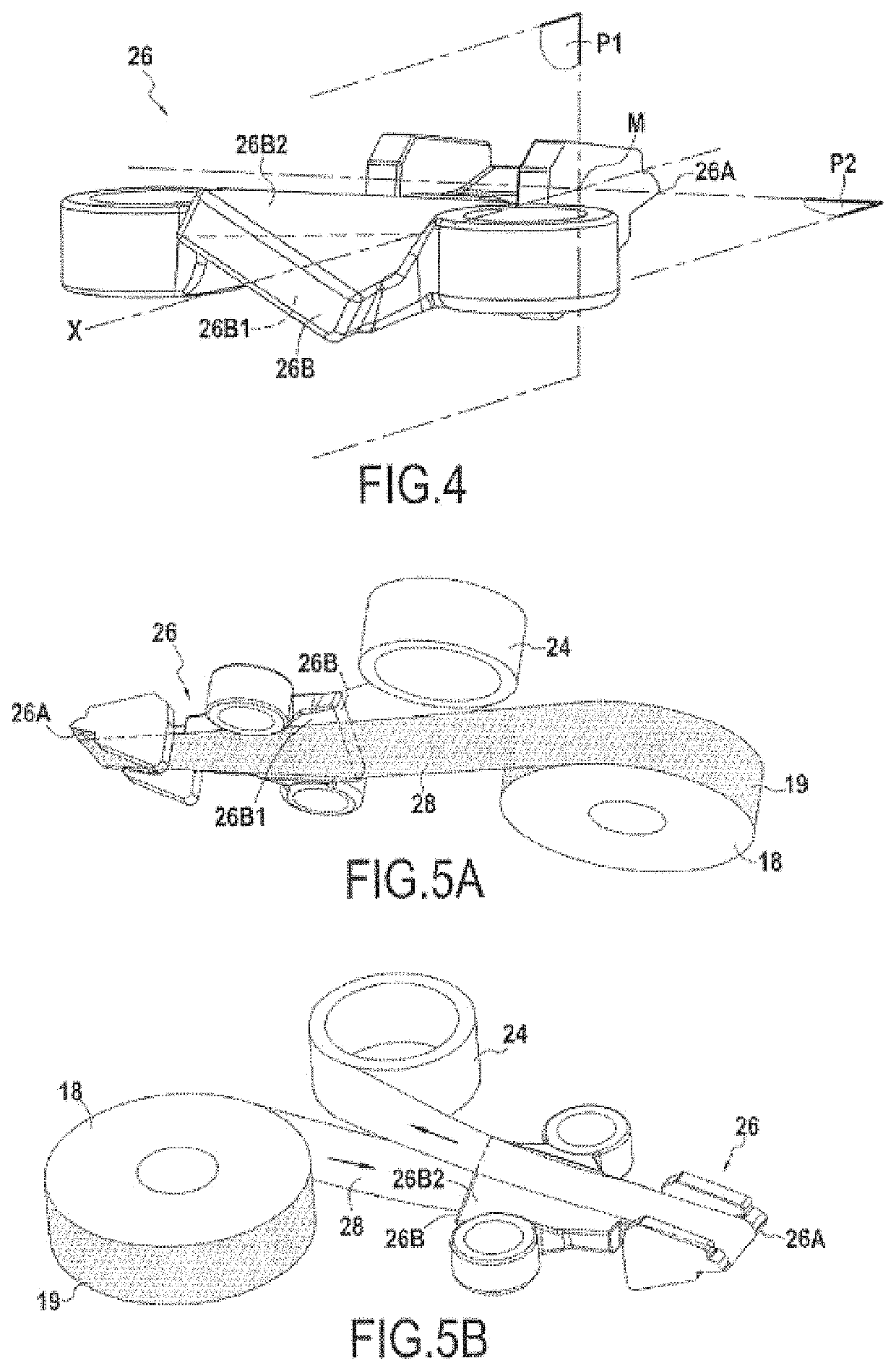
[0028]Such offsetting of the bearings prevents interference between the two windings and the tape exiting / entering the windings, which further optimizes the position of the bearings in relation to the median plane and ensures a better alignment in the direction perpendicular to the application plane of each winding, and thus of the tape, with the corresponding portions of the applicator tip. This further reduces the stresses undergone by the tape.
[0030]Such a configuration enables the windings to be even better positioned in relation to the applicator tip, which further reduces the stresses undergone by the tape.

Problems solved by technology

Among the known manual devices of application by tape, the coating carried by the tape is often damaged before its application, particularly while the tape is travelling from the supply reel to the applicator tip.

Method used


Image

  • Manual device for applying a coating to a support by means of tape
  • Manual device for applying a coating to a support by means of tape
  • Manual device for applying a coating to a support by means of tape

Examples


Embodiment Construction

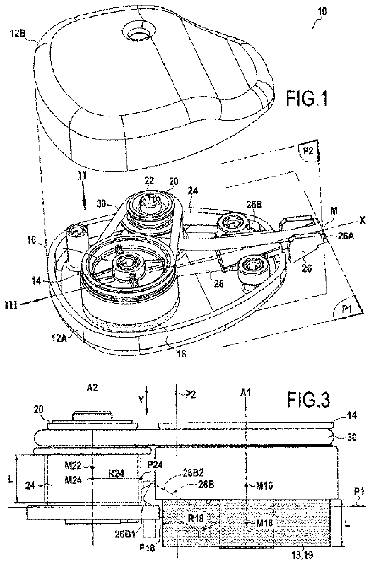
[0037]FIG. 1 shows a manual device 10 for applying a coating to a support by means of tape comprising a case having, in this embodiment, a first part of the case 12A and a second part of the case 12B, the case receiving a supply reel 14 mounted on a first bearing 16 and comprising a first winding of tape 18, a take-up reel 20 mounted on a second bearing 22 and comprising a second winding of tape 24 and an applicator tip 26. In this embodiment, the supply reel 14 and take-up reel 20 are coupled in rotation by a band 30, but clearly any other means of coupling these two reels in rotation can be envisaged. Similarly, in this embodiment the bearings 16 and 22 are formed by spindles integral with the first part of the case 12A, but any other configuration can be envisaged. For example, the bearings can be integral with a refill cartridge, forming a distinct piece of the case.

[0038]The applicator tip 26 has an application edge 26A and a guide portion 26B. The tape 28 extends, from upstrea...


PUM

PropertyMeasurementUnit
angleaaaaaaaaaa
angleaaaaaaaaaa
angleaaaaaaaaaa

Abstract

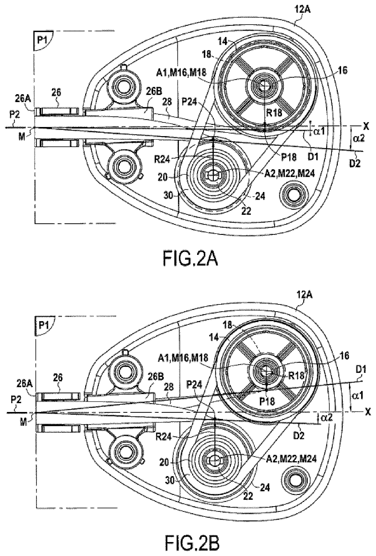
A manual device for applying a coating to a support by means of tape, in which a first angle formed between the median plane of the applicator tip and the half-line extending from the middle of the application edge of the applicator tip and passing through the point arranged at the intersection of the outer periphery of the first winding and the radius of the first winding perpendicular to the median plane, is between −1° and 10°, whereas a second angle formed between the median plane and the half-line extending from the middle of the application edge and passing through the point arranged at the intersection of the outer periphery of the second winding and the radius of the second winding perpendicular to the median plane, is between 1° and 10°.

Description

CROSS REFERENCE TO RELATED APPLICATION(S)[0001]This application is a National Stage Application of International Application No. PCT / FR2018 / 052266, filed on Sep. 17, 2018, now published as WO2019 / 058049, and which claims priority to French Application No. FR1758718, filed on Sep. 20, 2017.TECHNICAL FIELD[0002]The disclosure concerns the field of manual devices for applying a coating to a support by means of tape. These devices are sometimes known by the name of “mouse” or “tape applicator” and are used mainly, but not exclusively, in the office field. The coating can be, for example, glue or a white or colored coating.PRIOR ART[0003]Among the known manual devices of application by tape, the coating carried by the tape is often damaged before its application, particularly while the tape is travelling from the supply reel to the applicator tip. A need therefore exists in this regard.SUMMARY[0004]One aspect concerns a manual device for applying a coating to a support by means of tape c...

Claims


Application Information

Patent Timeline
Patent Type & Authority Patents(United States)
IPC IPC(8): B65H35/00B65H37/00
CPCB65H35/004B65H37/007B65H2301/33222
Inventor BEZ, ARNAUD
Owner SOC DITE SOC BIC
Learn More