Purification column
a technology of adsorption column and adsorption column, which is applied in the direction of other chemical processes, instruments, separation processes, etc., can solve the problems of increasing the cost of forming partition walls, increasing the pressure at the part, and difficulty in controlling the flow distribution of fluid in the adsorption column, so as to reduce the stagnation of fluid, and improve the adsorption efficiency
- Summary
- Abstract
- Description
- Claims
- Application Information
AI Technical Summary
Benefits of technology
Problems solved by technology
Method used
Image
Examples
example 2
[0103]Solid fibers in the same production lot of Example 1 were contained in a housing in the same condition of Example 1.
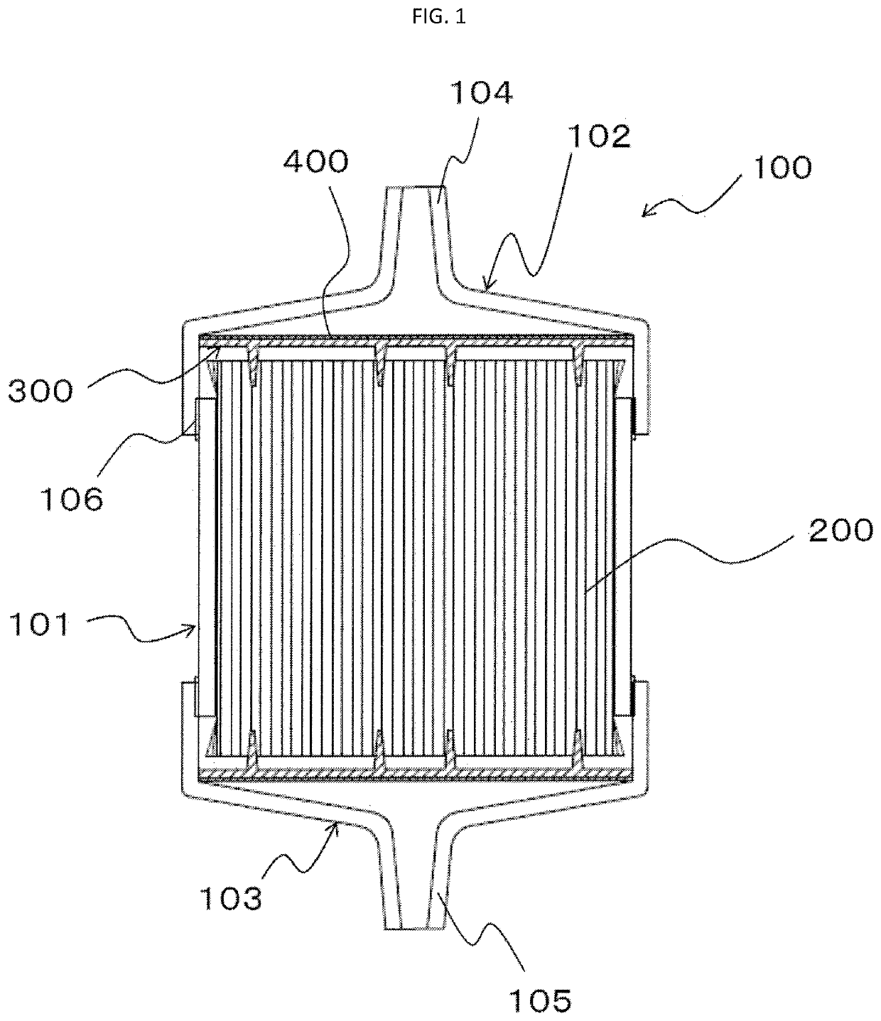
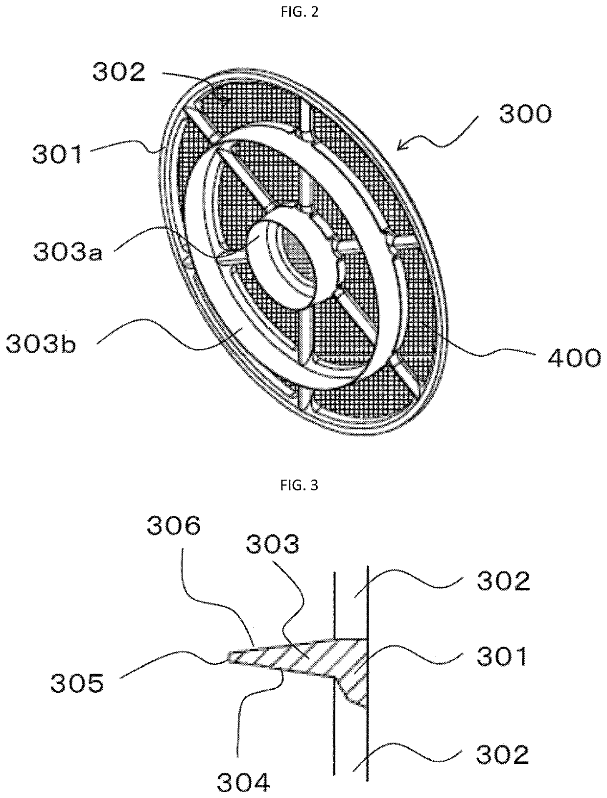
[0104]Similarly to Example 1, a distribution plate of the same type as shown in FIG. 2 with double ring-shaped salients was provided at the fiber bundle end face of the fluid supply side only. The widths of salient tips, the tip diameters of the salients, the inner periphery side diameter and the outer periphery side diameter were the same as Example 1, but the insertion lengths to the fiber bundle of the first salient at the center and the second salient at the outer periphery side were both 10 mm.
[0105]Then, a supply port having the same shape as shown in Example 1 was attached to the end face of housing at the fluid supply side. A fluid measuring jig having the same shape as shown in Example 1 was provided at the housing end face of the fluid discharge side.
[0106]The fiber bundle had packing rate of 55.9% like Example 1 at end faces of both the fluid supply si...
example 3
[0108]Solid fibers obtained in the same production lot of Example 1 were contained in a housing in the same condition of Example 1.
[0109]Next, a distribution plate of the same type as shown in FIG. 2 with double ring-shaped salients was provided at the fiber bundle end face of the fluid discharge side only. The insertion lengths to the fiber bundle of the first salient at the center and the second salient at the outer periphery side were both 4 mm. The widths of salient tips were 0.2 mm. The first salient had tip diameter of 14.3 mm, inner periphery side diameter of 13.6 mm and outer periphery side diameter of 15.4 mm. The second salient had tip diameter of 45.7 mm, inner periphery side diameter of 45.3 mm and outer periphery side diameter of 47.1 mm.
[0110]Then, a supply port having the same shape as shown in Example 1 was attached to the end face of housing at the fluid supply side. A fluid measuring jig having a sectioned cross-section area of the same as the area sectioned by the...
example 4
[0113]Solid fibers obtained in the same production lot of Example 1 were contained in a housing in the same condition of Example 1.
[0114]Next, distribution plates of the same type as shown in FIG. 2 with double ring-shaped salients were provided at both end faces of the fiber bundle. The distribution plate provided at the fluid bundle supply side had the same shape of the distribution plate shown in Example 2 while the distribution plate provided at the fluid bundle discharge side had the same shape of the distribution plate shown in Example 34.
[0115]Then, a supply port having the same shape as shown in Example 1 was attached to the end face of housing at the fluid supply side. A fluid measuring jig having the same shape as shown in Example 3 was provided at the housing end face of the fluid discharge side.
[0116]The fiber bundle had packing rate of 55.9% like Example 1 at both end faces before inserting the distribution plate in this configuration. Like Example 1, the end face of fl...
PUM
| Property | Measurement | Unit |
|---|---|---|
| diameter | aaaaa | aaaaa |
| particle diameter | aaaaa | aaaaa |
| particle diameter | aaaaa | aaaaa |
Abstract
Description
Claims
Application Information
 - R&D
- Intellectual Property
- Life Sciences
- Materials
- Tech Scout
- Unparalleled Data Quality
- Higher Quality Content
- 60% Fewer Hallucinations
Browse by: Latest US Patents, China's latest patents, Technical Efficacy Thesaurus, Application Domain, Technology Topic, Popular Technical Reports.
© 2025 PatSnap. All rights reserved.Legal|Privacy policy|Modern Slavery Act Transparency Statement|Sitemap|About US| Contact US: help@patsnap.com


