
Extendable sleeve for poured concrete deck

a tubular sleeve and concrete technology, which is applied in the field of poured concrete sleeve extension tubular sleeve, can solve the problems of degrading the performance of the diaphragm, degrading the diaphragm sealing with the pipe passing through the sleeve and diaphragm, and time-consuming and cumbersome cutting of the sleeve to length,

Active Publication Date: 2021-04-13
RELIANCE WORLDWIDE CORP
View PDF59 Cites 3 Cited by
  • Summary
  • Abstract
  • Description
  • Claims
  • Application Information

AI Technical Summary

Benefits of technology

The patent is about a cap for a tubular sleeve used in construction. The cap has ridges and a channel that separates them, and it is designed to fit tightly over the sleeve and be easily positioned. This design helps create a more uniform interlock in the concrete deck without any added stress or stabilizing structures, which reduces the chances of cracks and rust. The technical effect of this design is a more stable and reliable connection between the sleeve and the support structure.

Problems solved by technology

But that extendable sleeve uses a vertically-split base to connect to a metal frame that supports intumescent rings and that vertically-split base is cumbersome to assemble as it requires threaded fasteners to hold the parts securely together and it allows vertical misalignment of the vertically split parts of the base.
Moreover, a flexible diaphragm is clamped between a top of the base and a sleeve that is threaded onto the base and the threading rotation of the sleeve can damage the flexible diaphragm and can also distort the diaphragm, thereby degrading the diaphragm performance and sealing with the pipe passing through the sleeve and diaphragm during use.
But cutting the sleeve to length is time consuming, inaccurate and cumbersome.

Method used


Image

  • Extendable sleeve for poured concrete deck
  • Extendable sleeve for poured concrete deck
  • Extendable sleeve for poured concrete deck

Examples


Embodiment Construction

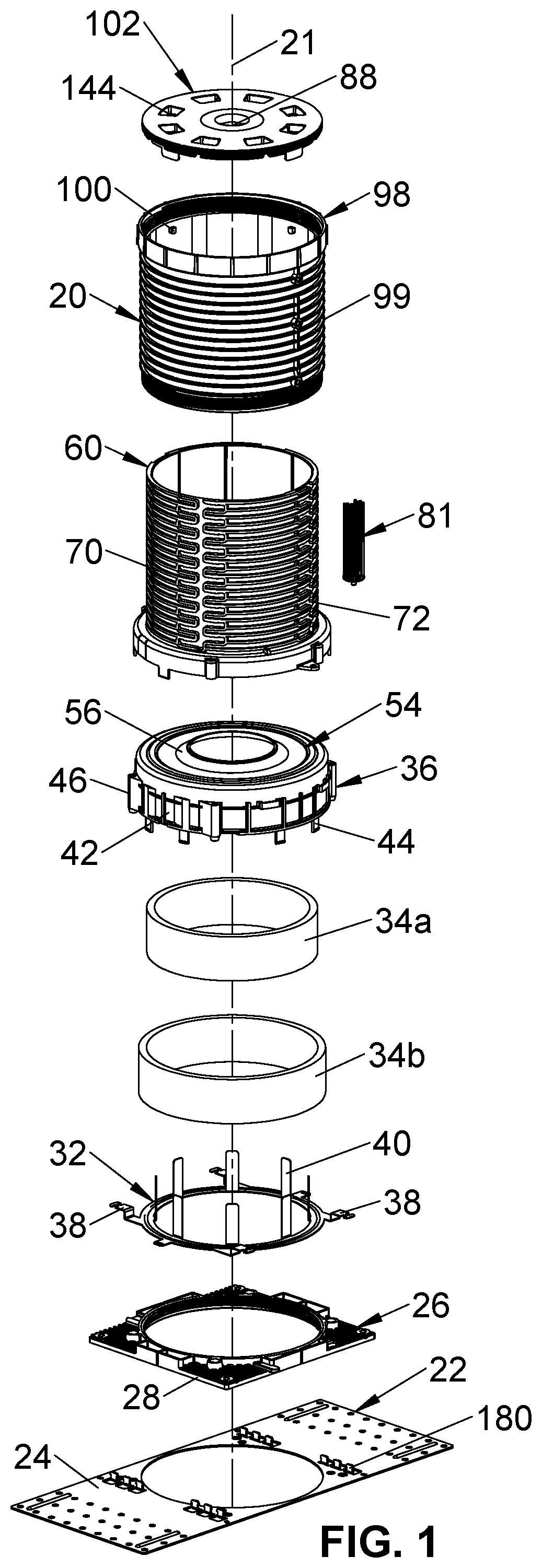
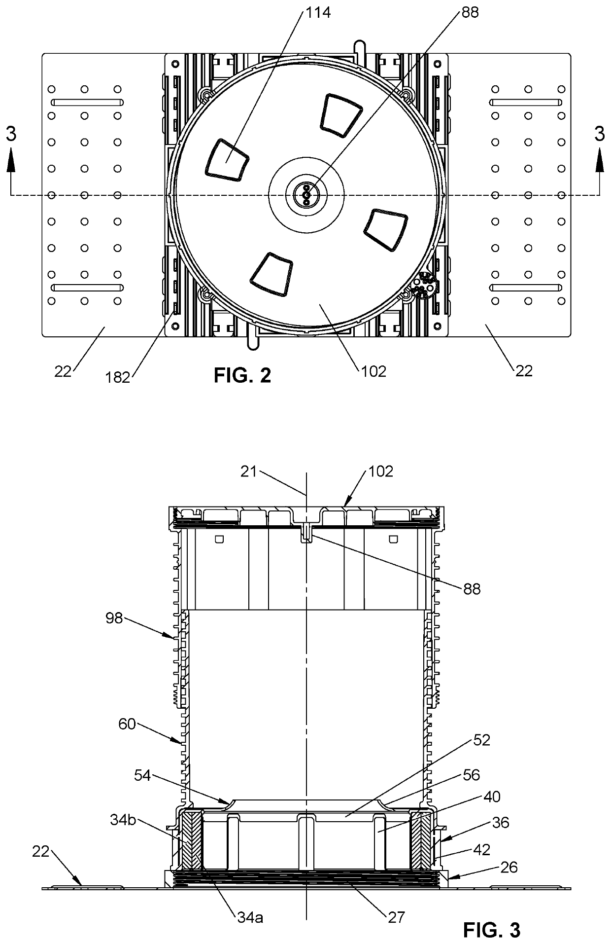
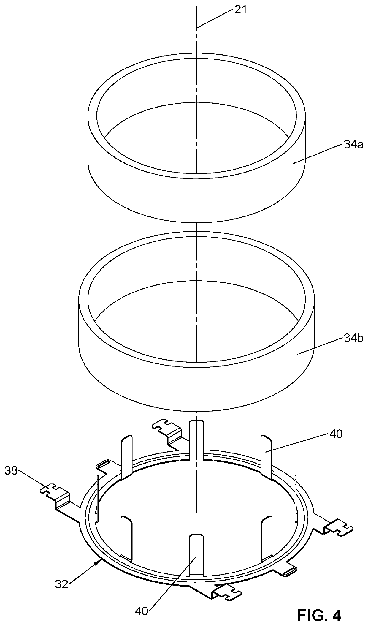
[0075]As used herein, the following part numbers refer to the following parts: 20—extendable sleeve assembly; 22—CD Plate; 24—opening in CD plate; 26—lower base; 27—base threads; 28—socket in lower base; 30—catches in lower base; 32—fire ring; 34—intumescent members; 36—upper base and seal assembly; 38—ring tab; 40—fingers on ring; 42—flange; 44—latch; 46—upper base sockets; 50—top plate; 52—inner flange; 54—flexible diaphragm; 56—diaphragm sidewall; 58—indentations; 59—position stop; 60—inner sleeve; 62—base of inner sleeve; 64—sleeve flange; 66—sealing projections; 70—first set of ridges; 72—second set of ridges; 74a, 74b—channels; 76—end segments; 78—engaging protrusion on end segment 76; 80—whisker support; 81—whisker assembly; 82—whiskers; 84—whisker base; 86—male whisker connector; 88—female whisker connector; 92—inner sleeve socket; 94—sleeve latch members; 96—catch; 98—outer sleeve; 99—ridges; 100—engaging posts; 102—first safety cap; 104—radial sockets; 106—external threads...


PUM


Abstract

An improved cap and assembly is provided for a poured concrete deck. The improved assembly has a diaphragm seal over-molded to a top plate having a depending sidewall that is snap-fit to a base containing a fire ring. A tubular sleeve is connected to the over-molded top plate by snap fit connections to the sidewall and by threaded fasteners passing through sockets in the sleeve, sidewall and base. The over-molded diaphragm has a funnel shape. A first sleeve cap has depending positioning tabs that may be broken off to adjust the cap height relative to the sleeve, with an inwardly extending latching surface engaging the sleeve when the tabs are removed. A second cap has inwardly extending tabs that fit into channels on the sleeve fit between ridges on the sleeve when rotated to adjustably position the second cap on the sleeve.

Description

CROSS-REFERENCE TO RELATED APPLICATIONS[0001]The application claims the benefit under 35 U.S.C. § 119(e) to Provisional Patent Application No. 62 / 609,215 filed Dec. 21, 2017, and Provisional Patent Application No. 62 / 657,519 filed Apr. 13, 2018 the entire contents of which are incorporated herein by reference.STATEMENT RE: FEDERALLY SPONSORED RESEARCH / DEVELOPMENT[0002]Not applicable.BACKGROUND[0003]An extendable tubular sleeve for poured concrete decks is described in U.S. Pat. Nos. 9,086,174 and 9,103,116. But that extendable sleeve uses a vertically-split base to connect to a metal frame that supports intumescent rings and that vertically-split base is cumbersome to assemble as it requires threaded fasteners to hold the parts securely together and it allows vertical misalignment of the vertically split parts of the base. Moreover, a flexible diaphragm is clamped between a top of the base and a sleeve that is threaded onto the base and the threading rotation of the sleeve can damag...

Claims


Application Information

Patent Timeline
Patent Type & Authority Patents(United States)
IPC IPC(8): E04C2/52E04B5/48A62C2/06E04B1/94F16L5/04F16L5/10
CPCE04B5/48A62C2/065E04B1/948F16L5/04F16L5/10E04G15/061
Inventor BROWN, LARRY D.COSLEY, JAMESHART, DENNISO'NEIL, VIRGIL
Owner RELIANCE WORLDWIDE CORP
Learn More