Optimized pipe handling system with quick loader arm

a technology of pipe handling and quick loader, which is applied in the direction of tubular articles, pipe laying and repair, domestic applications, etc., can solve the problems of increasing the overall cost of the construction project at hand, affecting the structural integrity of the joint, and “rough” handling of hot fusion joints, so as to reduce the potential for damage to the pipe, reduce the potential for tangential loading, and minimize the effect of adverse handling effects or severe bending strain

Active Publication Date: 2021-04-06
GAJESKE INC
View PDF7 Cites 1 Cited by
  • Summary
  • Abstract
  • Description
  • Claims
  • Application Information

AI Technical Summary

Benefits of technology

[0028]In the most preferred form of the inventive method, an exit-end support is removably attached to the mobile sub-frame of the fusion machine to allow a section of fused pipeline to exit the fusion machine at an elevated position relative to the ground as the fusion machine and attached exit-end support move axially in an opposite direction along a growing pipeline. In this way, the fused section of pipe is lowered to the ground following a natural curve between the exit-end support and the ground as the fused pipeline exits the exit-end support. The exit-end support can conveniently be made up of a base member and an upwardly extending frame member which terminates in a pipe receiving cradle designed to laterally stabilize a section of pipe to be fused while allowing the section of pipe to slide through the cradle during the fusing operation.
[0029]The centerline entrance and exit of the thermoplastic pipe from the fusion machine and the use of the exit-end support help to minimize any adverse handling effects or severe bending strain on a warm fused joint while also reducing potentially damaging drag and tangential loading on the fused pipe joint.

Problems solved by technology

The time that the crane crew sits idle represents lost efficiency and, along with other costs that accompany longer construction periods, increases the overall cost of the construction project at hand.
Another issue with this traditional usage of fusion machines is the “rough” handling of hot fusion joints.
Ignoring the cooling time and handling a joint roughly could compromise the structural integrity of the joint, i.e. the joint could yield or droop under too much stressor strain, such as when the fusion machine progresses to the next section of pipe.
The conveyer is additionally permanently attached to a given Fast Fusion™ machine and is not intended to be adaptable to other fusion machines.
However, the cooling is material-property limited, and rough handling of joints can still occur.
While Fast Fusion™ allows for all-weather fusion within a closed cab and a decrease in crew numbers, the cost of the machine is prohibitive for many potential owners.
Due due to the high cost of such complex equipment, many plastic pipe fusion companies cannot afford this type of machinery.
Fast Fusion™ machines are very heavy, requiring a permitted load on highways.
Since the machines are also complex, any break down involves obtaining replacement parts which can sometimes take weeks.
However, as discussed above, there are issues inherent in the traditional method of using fusion machines that highlight a need for a more efficient, simple, and cost-effective ways to quickly and efficiently fuse sections ofpipe in the pipeline construction industry without cost-prohibitive and heavy machinery.

Method used


Image

  • Optimized pipe handling system with quick loader arm
  • Optimized pipe handling system with quick loader arm
  • Optimized pipe handling system with quick loader arm

Examples


Embodiment Construction

[0036]The preferred version of the invention presented in the following written description and the various features and advantageous details thereof are explained more fully with reference to the non-limiting examples included and as detailed in the description which follows. Descriptions of well-known components and processes and manufacturing techniques are omitted so as to not unnecessarily obscure the principal features of the invention as described herein. The examples used in the description which follows are intended merely to facilitate an understanding of ways in which the invention may be practiced and to further enable those skilled in the art to practice the invention. Accordingly, the examples should not be construed as limiting the scope of the claimed invention.

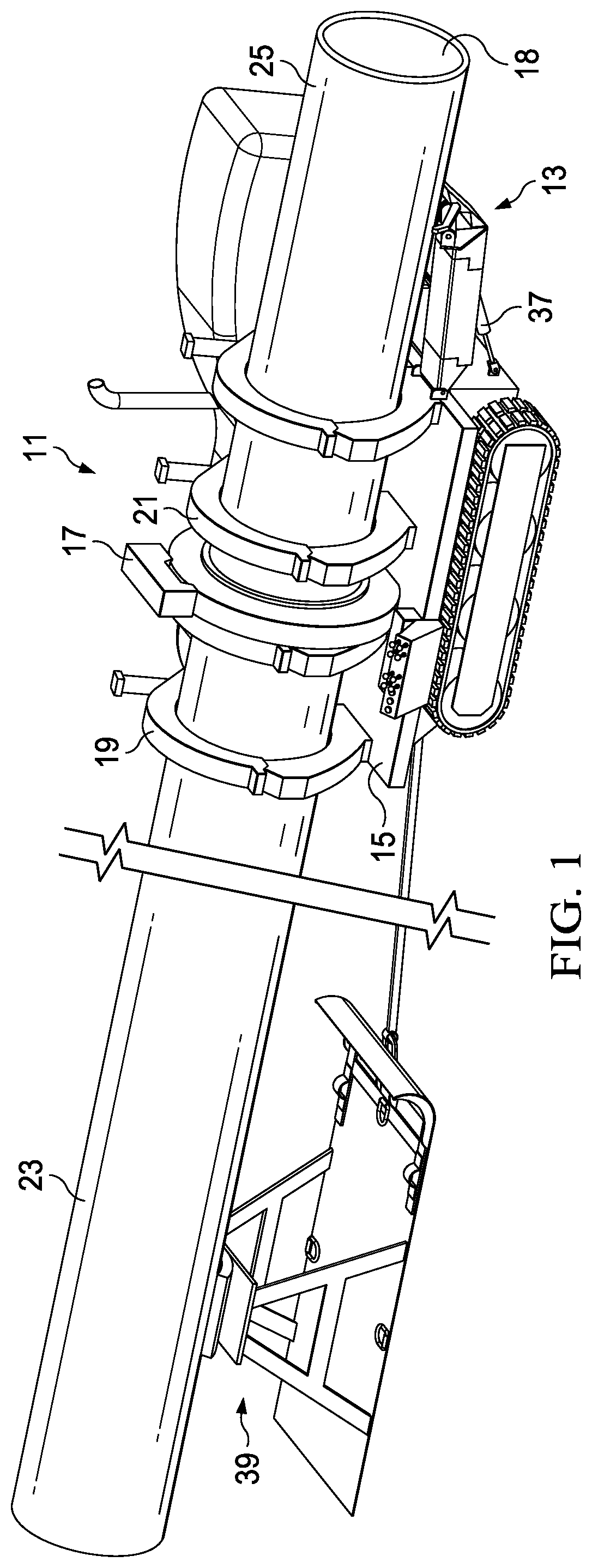
[0037]As has been briefly discussed, thermoplastic pipelines are used in a myriad of industries to transport fluids, including oil, gas, water, and sewage. Thermoplastic pipelines are often constructed at a jo...


PUM

PropertyMeasurementUnit
angleaaaaaaaaaa
frictional resistanceaaaaaaaaaa
distanceaaaaaaaaaa

Abstract

A method is shown for fusing sections of thermoplastic pipe together to construct continuous pipelines. A pipe loader arm is provided which can be attached to the mobile sub-frame of any number of commercially available fusion machines. The pipe loader arm scoops up and loads a new section of thermoplastic pipe to be fused into the fusion machine by feeding the pipe in an axial direction, rather than lifting the new section of pipe with a crane and vertically feeding it into the fusion machine. An exit-end support can be used to gradually lower the growing pipeline to the ground after the fusion step. The method described herein greatly reduces the time and increases the ease in which sections of pipe are fused to grow pipelines, while additionally making the process safer and protecting newly-made pipe joints from rough handling.

Description

BACKGROUND OF THE INVENTION1. Field of the Invention[0001]The present invention relates generally to the field of thermoplastic pipeline construction and, more specifically, to a method for fusing sections of thermoplastic pipe to form such a pipeline using a fusing machine equipped with an auxiliary pipe loading arm which loads the sections of pipe to be fused into the fusing machine axially as opposed to vertically.2. Description of the Prior Art[0002]Various industries utilize thermoplastic pipelines, such as polyethylene pipe, to transport fluids across great distances. A thermoplastic pipeline is typically provided to the jobsite in multiple smaller and more manageable pieces to allow for easier transport and installation. These smaller pieces are then joined together, as by fusing the pipe ends, to create a continuous pipeline.[0003]The fusing operation is carried out using a fusion machine. Such fusion machines are widely used in the industry and enable the welding of joints ...

Claims


Application Information

Patent Timeline
Patent Type & Authority Patents(United States)
IPC IPC(8): B29C65/02B29C65/20B29C65/78F16L1/06B29C65/00B29L23/00
CPCB29C66/5221B29C65/02B29C65/20B29C65/7802B29C65/7841B29C66/1142B29C66/73921B29C66/86521F16L1/065B29L2023/22B29C31/002F16L1/036
Inventor ABATIE, CHAD
Owner GAJESKE INC
Why Eureka
Try Eureka