
Technique for low-speed balancing of a rotor of a compressor for a gas turbine

a gas turbine and compressor technology, applied in the field of rotor balancing, can solve the problems of inability to accurately balance the rotor for operational speeds, difficult assembly of blades with movement possibilities, and inability to accurately balance the rotor, so as to improve the accuracy of low-speed balancing of rotor blade assemblies, reduce movement or prevent movement

Active Publication Date: 2021-03-30
SIEMENS ENERGY GLOBAL GMBH & CO KG
View PDF22 Cites 0 Cited by
  • Summary
  • Abstract
  • Description
  • Claims
  • Application Information

AI Technical Summary

Benefits of technology

[0010]Thus, an object of the present disclosure is to provide a technique that accomplishes the beneficial effects of operational-speed balancing or high-speed balancing without actually having to operate the compressor stage blades assembly at operational speeds or high speeds in the course of the balancing operation, or in other words to say to achieve operation speed balance for the compressor stage blades assembly while performing low-speed balancing.

Problems solved by technology

Balancing of rotors having such a compressor stage blades assembly that have possibilities of movement of the blades is difficult because the blade movements cause unbalance variation from run to run of low-speed balancing.
With blade movement within the compressor stage blades assembly, the low-speed balancing cannot accurately balance the rotor for operational speeds, because during low-speed balancing the compressor stage blades assembly is rotated at speeds for example 800 rpm, which is much lower than the operational speeds which for example may be between 8000 rpm to 14000 rpm or more.
Thus the conventionally known methods for low-speed balancing are insufficient to balance rotors having the compressor stage blades assembly, where possibilities of blade movement within the assembly exist, for operational speeds.
However, there are significant problems of feasibility and cost to be overcome in balancing the rotors with such compressor stage blades assembly if rotated at operational speeds.

Method used


Image

  • Technique for low-speed balancing of a rotor of a compressor for a gas turbine
  • Technique for low-speed balancing of a rotor of a compressor for a gas turbine
  • Technique for low-speed balancing of a rotor of a compressor for a gas turbine

Examples


Embodiment Construction

[0036]Hereinafter, above-mentioned and other features of the present technique are described in details. Various embodiments are described with reference to the drawing, wherein like reference numerals are used to refer to like elements throughout. In the following description, for purpose of explanation, numerous specific details are set forth in order to provide a thorough understanding of one or more embodiments. It may be noted that the illustrated embodiments are intended to explain, and not to limit the invention. It may be evident that such embodiments may be practiced without these specific details.

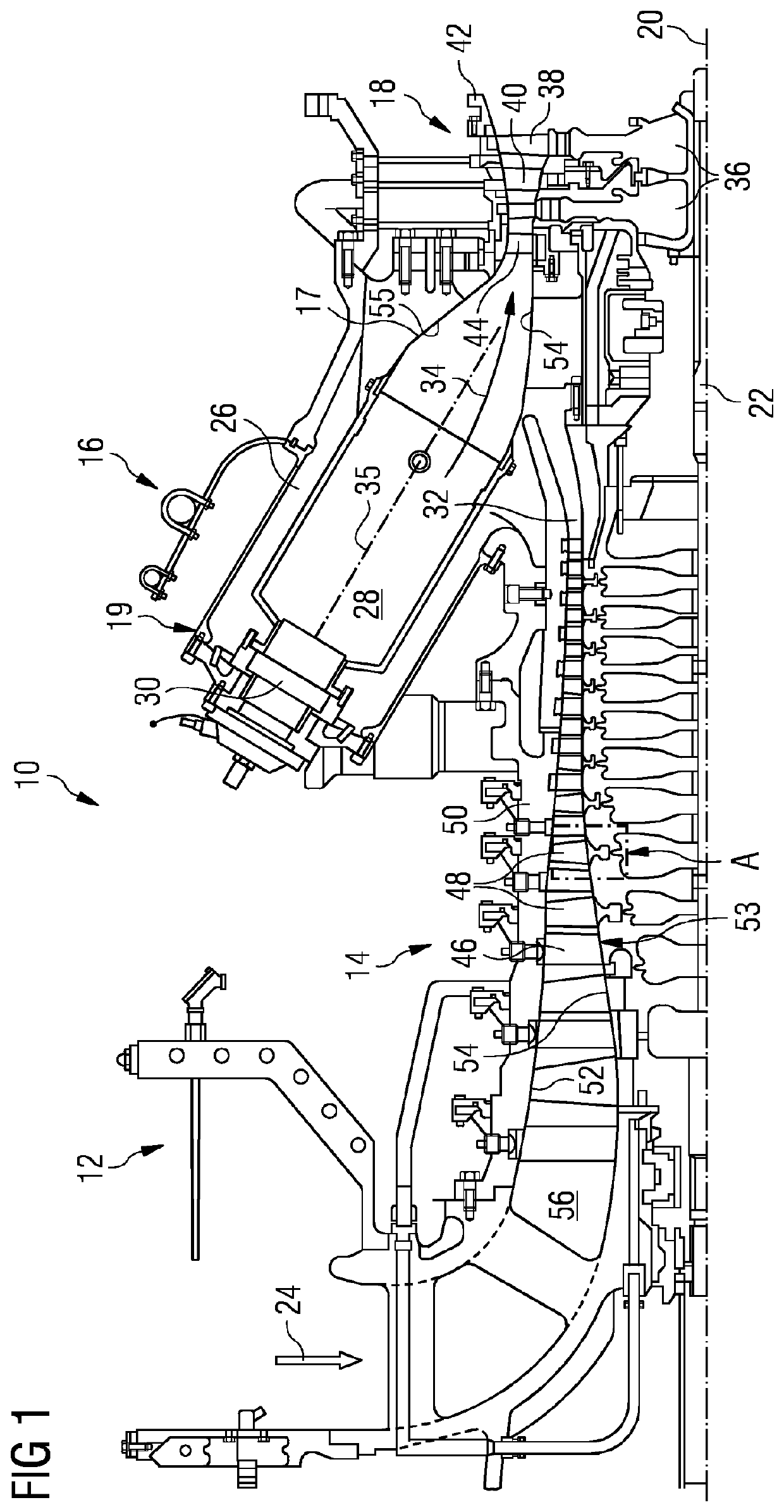
[0037]FIG. 1 shows an example of a gas turbine engine 10 in a sectional view. The gas turbine engine 10 comprises, in flow series, an inlet 12, a compressor or compressor section 14, a combustor section 16 and a turbine section 18 which are generally arranged in flow series and generally about and in the direction of a rotational axis 20. The gas turbine engine 10 further comprise...


PUM


Abstract

A method for low-speed balancing of a rotor having at least one compressor stage blades assembly includes a row of blades circumferentially arranged with circumferential clearance. Two or more blades are located blades, each having an angular position in the assembly, at which the located blades are maintained. The located blades define sectors. Each sector includes movable blades and sectoral circumferential clearances. The movable blades, for each sector, are circumferentially adjusted such that the sectoral circumferential clearance of the sector moves circumferentially downstream relative to the movable blades with respect to a rotational direction when the assembly is rotated. Relative position of the sectoral circumferential clearances and the movable blades within each sector is maintained by inserts. A measure of unbalance is determined for the rotor in low-speed balancing conditions. The inserts are removed after low speed balancing and the clearances are kept to accommodate the blade root thermal expansion.

Description

CROSS REFERENCE TO RELATED APPLICATIONS[0001]This application is the US National Stage of International Application No. PCT / EP2017 / 072090 filed Sep. 4, 2017, and claims the benefit thereof. The International Application claims the benefit of European Application No. EP16188471 filed Sep. 13, 2016. All of the applications are incorporated by reference herein in their entirety.FIELD OF INVENTION[0002]The present technique relates generally to balancing of rotors and, more particularly to techniques of low-speed balancing of gas turbine compressor rotors with compressor stage blades assemblies.BACKGROUND OF INVENTION[0003]For rotors that operate below their critical speed, conventionally low-speed balancing is sufficient to balance the rotor before installation or operation of the rotor, since such rotors do not operate at speeds that cause conformational changes in the rotor.[0004]Particularly for rotors having one or more compressor stage blades assemblies where a number of compresso...

Claims


Application Information

Patent Timeline
Patent Type & Authority Patents(United States)
IPC IPC(8): F01D5/02F01D5/30
CPCF01D5/027F01D5/303F01D5/3038F01D25/285F04D29/662G01M1/16
Inventor MENG, ZHIQIANG
Owner SIEMENS ENERGY GLOBAL GMBH & CO KG
Learn More