
Torque tool

Active Publication Date: 2021-02-23
WILSON JR DAVID
View PDF9 Cites 2 Cited by
  • Summary
  • Abstract
  • Description
  • Claims
  • Application Information

AI Technical Summary

Benefits of technology

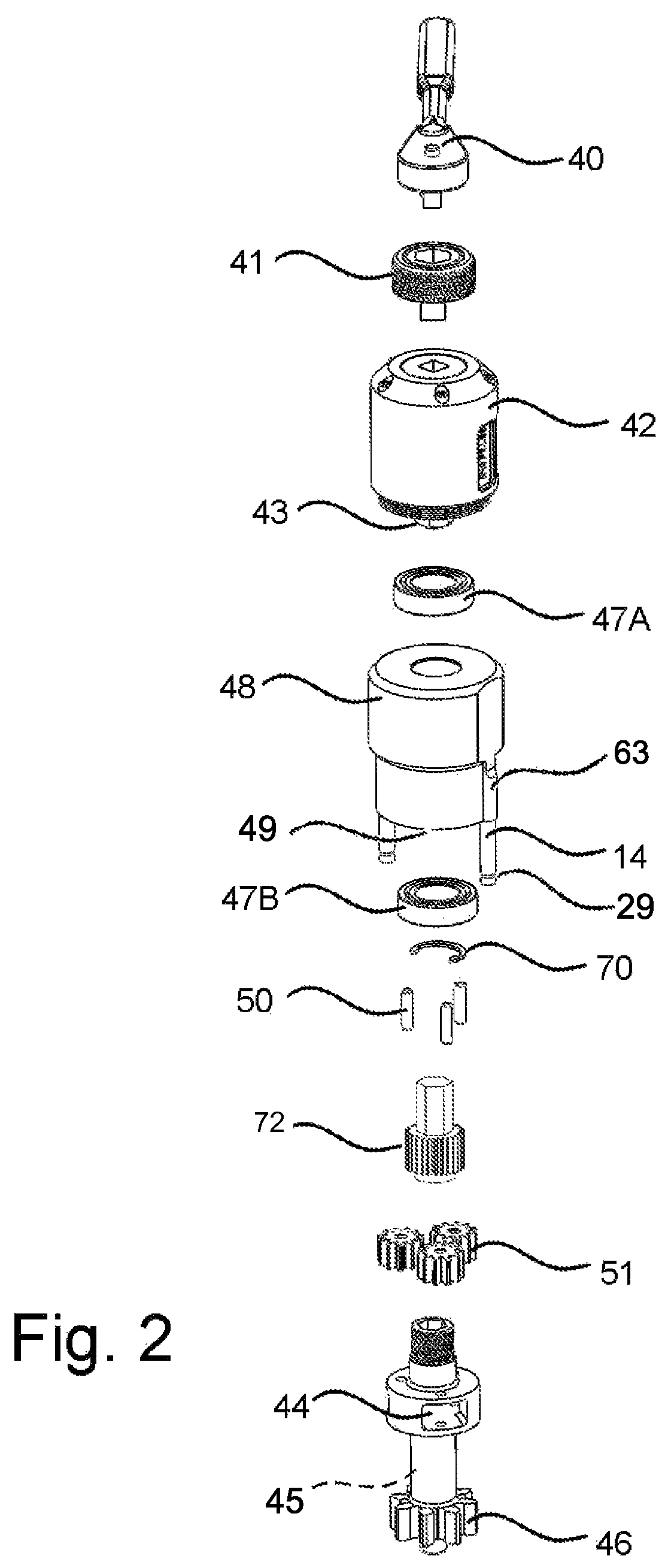
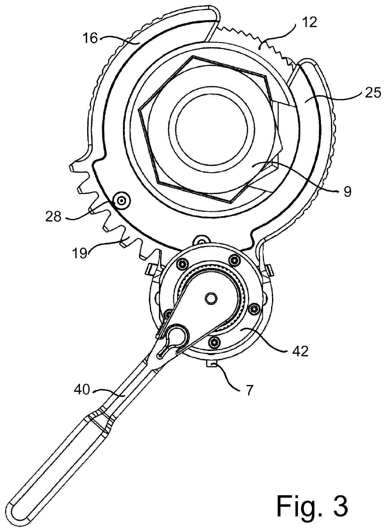
The present invention is a powerful and compact ratcheting crowfoot style wrench with integrated gear teeth cut around its perimeter. It is designed to be used with a wide range of fixed jaw or ratcheting open-end crowfoot style wrench heads, and can apply precise torque values to install fluid fittings with common hand tools or easily adapted for engagement by electric or pneumatic power tools. The tool's configuration allows for high torque values when required, and ensures accurate tightening of fittings by applying a measured torque value. The tool's accuracy is verified through strain gauge and torque testing machine comparisons. The bottom face of the housing is provided with pivoted blades for capture or release of a slotted circular pivot hub, and the ratchet drive socket is rotated by a pinion drive gear coupled with a planetary torque multiplier to provide torque multiplication. The tool is easily adapted for automatic reciprocating rotation and is configured for various types of fittings. Its profiles and configurations allow for effective torque application and ease of installation or removal of fittings.

Problems solved by technology

Thereafter, installing the fittings and finally, replacing the components that were removed would be reinstalled which wasted both time and money.
Fitting sizes finally reached a point where manual assembly started to become extremely difficult or even impossible.
The torque required to install some fittings exceeds 250 ft. lbs. and as a result, these manually operated ratchet tools reached the limit of their utility.
Since this is nearly impossible, wrench extensions two feet long still required 125 pounds of force to rotate the wrench handle.
The major problem is that many operating envelopes provide less than ten inches of total clearance around the perimeter of the fitting, thus again stopping the assembly.

Method used


Image

  • Torque tool
  • Torque tool
  • Torque tool

Examples


Embodiment Construction

[0026]The invention will now be described by way of example with reference to the accompanying drawings showing a preferred embodiment of power wrench assembly.

[0027]The body of the ratchet housing 16 is provided with an outwardly extending flange forming a sector geared annulus 19 around the outside perimeter of the housing at a position opposite the slotted opening 24 at the front of the housing extending into a ratchet gear hub receiving counter bored pocket 15 that is provided in the upper surface of the housing for rotatably enclosing a ratchet wheel 12 provided with upper and lower hubs, FIG. 4 which extend into circular openings at a first end into the housing and through the housing cover 25 at a second end provided to support rotation of the hubs. Two spaced apart pockets 16 are counter bored into the housing to hold spring 27, FIG. 7 biased and pivoted ratchet dogs 26 in contact with an inserted slotted ratchet wheel 12 to translate reciprocating rotation of the sector gea...


PUM


Abstract

A reciprocating apparatus for high torque transfer to a fitting, including tightening or loosening, having two coaxially synchronized engageable drive members provided with a sector geared radial flange engageable with an engageable rotatable drive gear, one internally supported split ratchet gear and drive socket maintained in contact with a spring biased ratchet pawl, together simultaneously rotatable in a first driving direction and independently disengageable in a second direction for reciprocative advancement of a ratchet geared socket in driving engagement with a fitting.

Description

FIELD OF INVENTION[0001]This invention relates to fitting manipulating apparatuses such as wrenches, sockets and socket drivers, and more particularly, relates to slotted ratchet wrenches operable with fluid fittings, fasteners, valves, connectors, pumps and the like.BACKGROUND OF THE INVENTION[0002]Originally, tube fittings were installed onto valves, “T”-unions, cross unions and adapters connecting tubing with only two hand wrenches. One wrench used to hold the fitting body and other wrench to tighten the fitting. Torque values were determined by the mechanic's sense of feel. This resulted in varied results from one mechanic to the next. This required that the mechanic have enough space to manipulate two open end wrenches without obstruction.[0003]When inadequate space was available, the mechanic would remove adjacent obstructions until enough working room was created to manipulate wrench handles. Thereafter, installing the fittings and finally, replacing the components that were ...

Claims


Application Information

Patent Timeline
IPC IPC(8): B25B13/46B25B23/14B25B13/08B25B17/02B25B13/48B25B23/00
CPCB25B13/467B25B13/08B25B13/481B25B17/02B25B23/0007B25B23/14
Inventor WILSON, JR., DAVID
Owner WILSON JR DAVID
Learn More