
Screw and method of use

a technology of screw and screw head, which is applied in the field of orthopedics and repair of fractures, can solve the problems of increasing the probability of error, damage or fracturing of the femoral head or neck of the patient, and increasing the difficulty of the procedure, so as to reduce the number of steps required, precise screw positioning, and the effect of reducing the inventory of screws

Inactive Publication Date: 2008-07-24
ALEXA MEDICAL
View PDF71 Cites 67 Cited by
  • Summary
  • Abstract
  • Description
  • Claims
  • Application Information

AI Technical Summary

Benefits of technology

[0007]A system of orthopedic repair and joint replacement reduces the number of steps required for completing a procedure and provides a device that may be implanted remotely. A remote operation allows active use of x-ray radiation during reaming and / or drilling operations and placement of the first portion of a two-part, orthopedic screw.
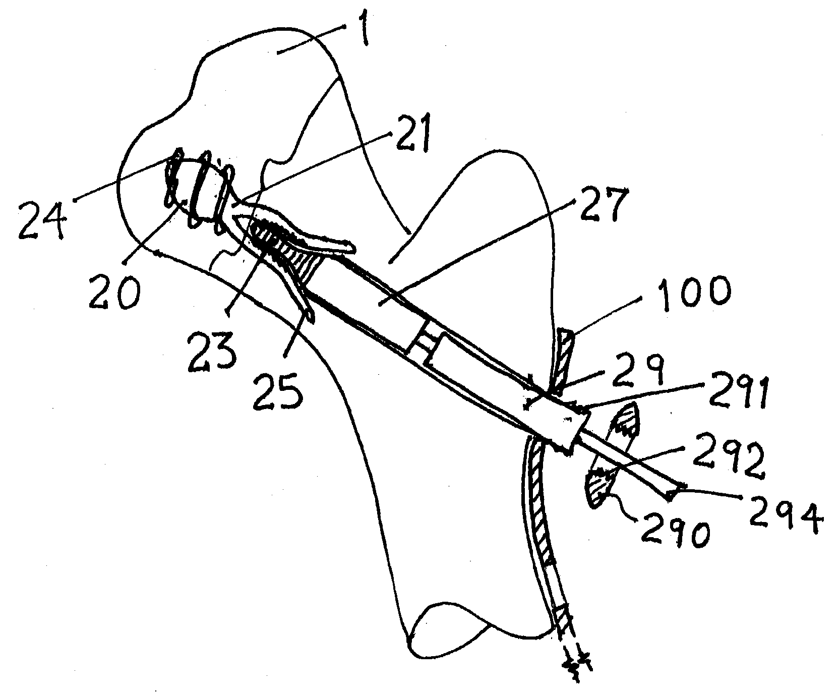
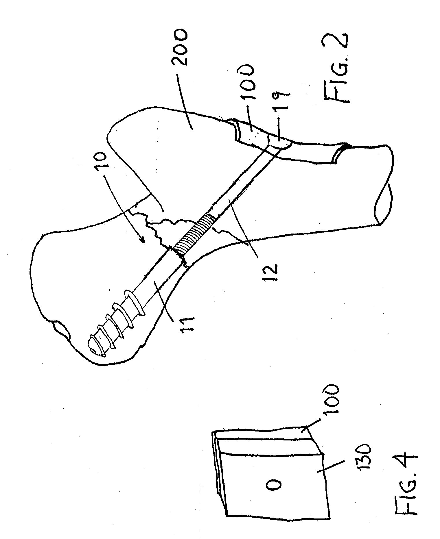
[0009]For example, a screw and retainer system has been developed that reduces the number and improves the outcome for patients requiring repair of fractures in bones. In one example, a two-part screw has two portions. A first portion has a thread for engaging cancellous bone within a portion of a bone on one side of a fracture. The second portion is capable of mating with the first portion and is coupled to a retention mechanism that couples a portion of the bone on the opposite side of the fracture to the portion of bone having the first portion of the screw threaded therein. By tightening the second portion, compression may be exerted that closes the fracture, applies compression across the fracture and improves the rate of healing of the fracture.

Problems solved by technology

This procedure requires many steps to form the hole and to insert and fix the lag screw, which make the procedure time consuming and difficult to accomplish successfully even for a skilled surgeon who has performed many operations using the procedure.
Other procedures are known that use multiple lag screws for fixation, which increases the difficulty of these procedures and increases the chances of an error and damaging or fracturing of the femoral head or neck of the patient.

Method used


Image

  • Screw and method of use
  • Screw and method of use
  • Screw and method of use

Examples


Embodiment Construction

[0027]The examples described and drawings rendered are illustrative and are not to be read as limiting the scope of the invention as it is defined by the appended claims.

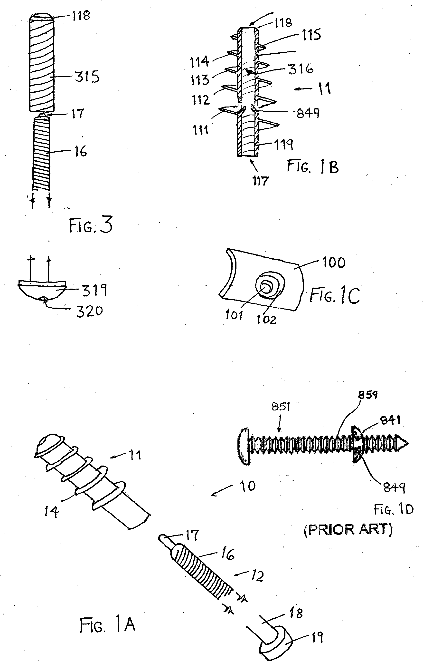
[0028]In FIG. 1A, an example of a two-part, orthopedic screw 10 comprises a first portion 11 and a second portion 12 that is capable of being coupled to the first portion, such as by threading a coupling portion 16. Alternatively, the coupling mechanism of the coupling portion 16 may be a one way latching mechanism such as used in plastic zip strips (also referred to as cable ties) or any other coupling mechanism, which has the advantage of locking the second portion 12 in the first portion. A locking or latching mechanism may be incorporated with a threaded coupling mechanism, such as a lock tight adhesive, a retaining pin, or any other mechanism for fixing the coupling portion 16, when it is located in its final position. The second portion 12 is coupled at an opposite end 18 with a cap 19 in the example shown in ...


PUM


Abstract

A two-part screw system for use in bone repair and joint replacement includes a first portion and a second portion capable of mating with the first portion. The first portion includes a thread for engaging cancellous bone within a portion of a bone on one side of a fracture. The second portion is coupled to a retention mechanism that couples a portion of the bone on opposite sides of the fracture to a portion of the bone having the first portion of the two-part screw.

Description

FIELD OF THE INVENTION[0001]The field relates to orthopedics and repair of fractures and wear to load bearing bones and joints, especially when a screw bone must be fixed in a bone of a patient.BACKGROUND[0002]FIG. 1D illustrates a known ratchet mechanism for a quick connector. The pin 851 has ridges 859 formed on the exterior. The connector 841 has latches 849 capable of latching with the ridges 859 allowing the pins 851 to be inserted into the connector 841 but preventing removal of the pin 851.[0003]For example, a Gamma™ nail system is known that has an operative technique to repair fractures in a femur, a femoral neck and the like. An x-ray template or goniometer is used to pre-operatively plan the insertion of a nail into a cavity formed in the femur. This procedure reams the femur, extends the nail into the reamed cavity in the femur, and then the nail is used with a targeting device and a wire to drill a hole into the femoral neck that precisely locates a lag screw through a ...

Claims


Application Information

Patent Timeline
Patent Type & Authority Applications(United States)
IPC IPC(8): A61B17/56A61B17/58
CPCA61B17/7001A61B17/7043A61B17/7056A61B2017/8655A61B17/8085A61B17/864A61B17/8685A61B17/8028
Inventor STINNETTE, ALBERT
Owner ALEXA MEDICAL
Learn More