Boot attachment method and constant velocity universal joint
a technology of constant velocity and mounting method, which is applied in the direction of bellows, mechanical devices, couplings, etc., can solve the problems of increasing the manufacturing cost required for assembly of constant velocity universal joints and difficulty in achieving highly accurate fastening while dealing, so as to reduce the size and weight of high-frequency induction heating devices, reduce the size and weight of high-frequency heating devices, and ensure the effect of stability
- Summary
- Abstract
- Description
- Claims
- Application Information
AI Technical Summary
Benefits of technology
Problems solved by technology
Method used
Image
Examples
example 1
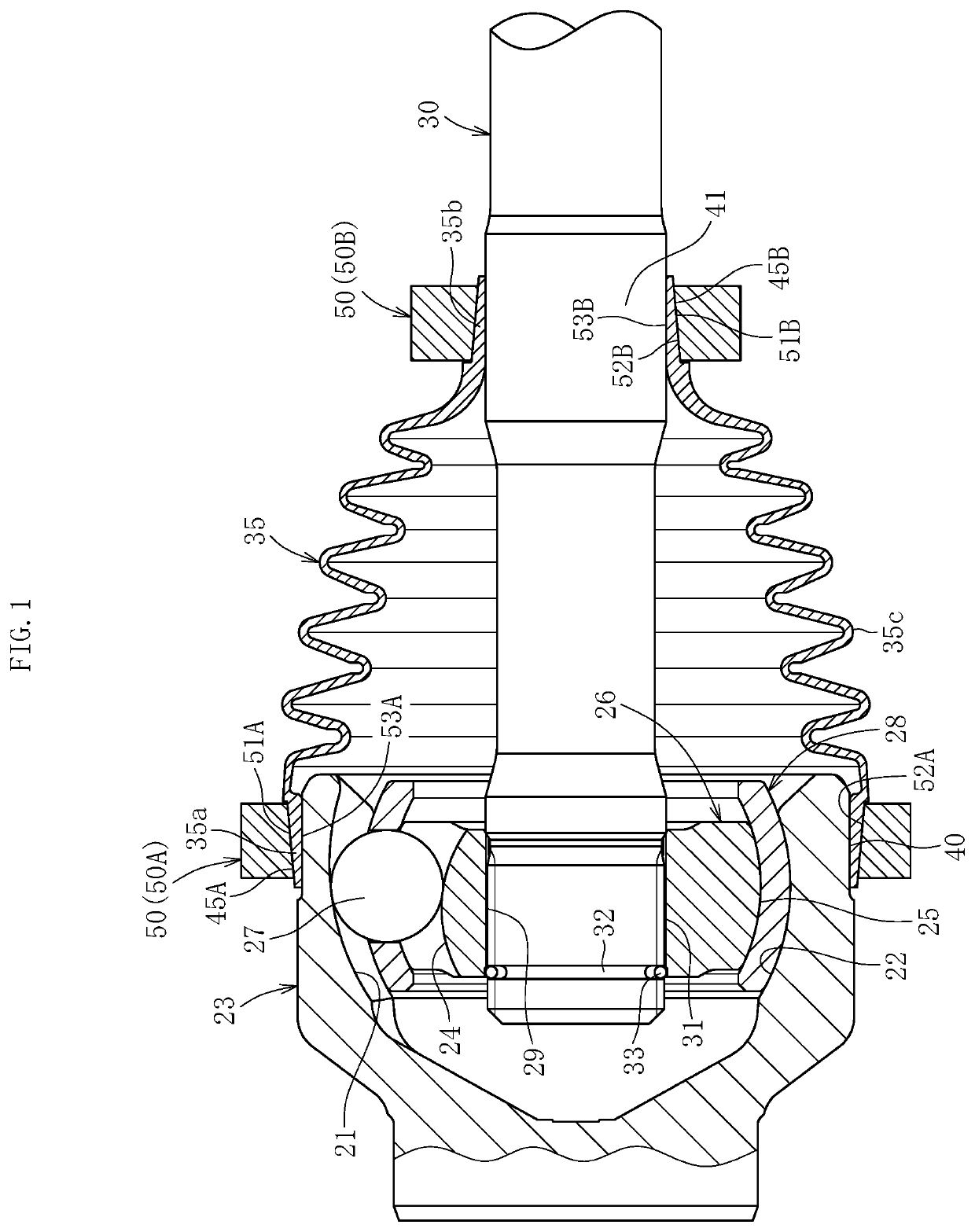
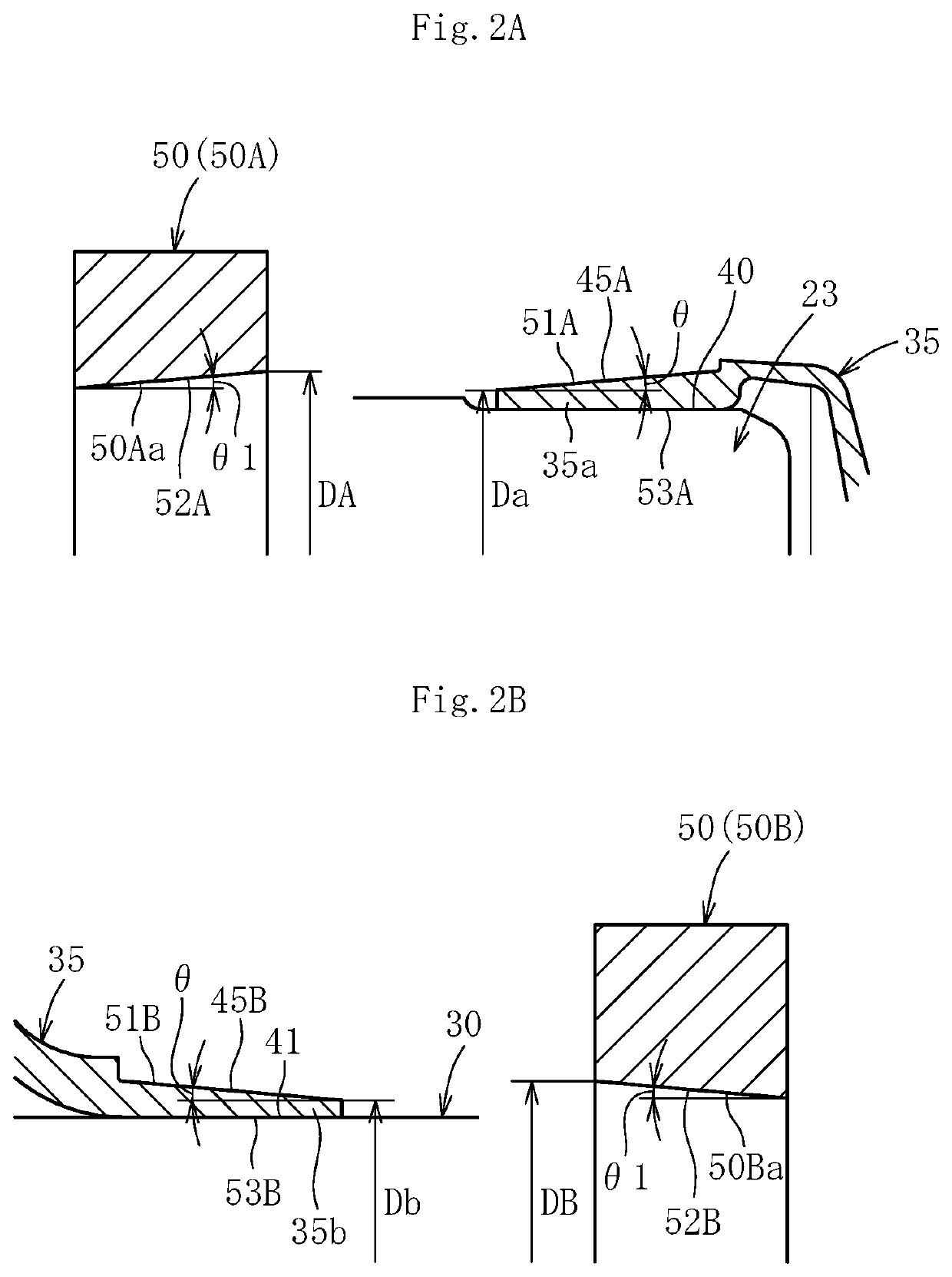
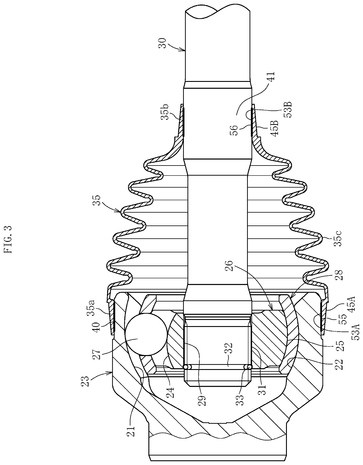
[0181]The interference between the boot end portion and the shaft was changed, and the ease of mounting of the boot and the joining strength for each interference were studied. The results are shown in the following Table 1 and Table 2. Table 1 and Table 2 are record tables with regard to an interference between an inner diameter (diameter) of the boot end portion and an outer diameter (diameter) of the receiving surface of the mating member. In Table 1, connection between the boot end portion (mounting portion) 35b and the shaft 30 is shown, in a case in which an inner diameter dimension of the boot end portion (mounting portion) 35b is 22 mm (diameter). In Table 2, connection between the boot end portion (mounting portion) 35a and the outer joint member (outer ring) 23 is shown, in a case in which an inner diameter dimension of the boot end portion (mounting portion) 35a is 70 mm (diameter). In Table 1 and Table 2, the comprehensive evaluation of “excellent” is denoted by CD. The ...
example 2
[0185]A grease leakage test was conducted for the boot having the boot end portion mounted and fixed to the shaft through use of coils having different shapes of the mating surface. Results thereof are shown in the following Table 3. For this test, the fixed type constant velocity universal joint illustrated in FIG. 5 was used, and a swing angle of from 25 degrees to 40 degrees and the rotation speed of 500 rpm were set.
[0186]
TABLE 3StraightLabyrinth 1Labyrinth 2Coil Mating SurfaceGrease Leakage Test50 hours70 hours85 hours
[0187]According to the results, the straight mating surface having no stepped structure caused leakage after 50 hours. The labyrinth 1 (stepped structure illustrated in FIG. 7) did not cause leakage after operation for 70 hours. The labyrinth 2 (stepped structure illustrated in FIG. 12) did not cause leakage after operation for 85 hours.
PUM
| Property | Measurement | Unit |
|---|---|---|
| taper angle | aaaaa | aaaaa |
| depth | aaaaa | aaaaa |
| depth | aaaaa | aaaaa |
Abstract
Description
Claims
Application Information
 - R&D
- Intellectual Property
- Life Sciences
- Materials
- Tech Scout
- Unparalleled Data Quality
- Higher Quality Content
- 60% Fewer Hallucinations
Browse by: Latest US Patents, China's latest patents, Technical Efficacy Thesaurus, Application Domain, Technology Topic, Popular Technical Reports.
© 2025 PatSnap. All rights reserved.Legal|Privacy policy|Modern Slavery Act Transparency Statement|Sitemap|About US| Contact US: help@patsnap.com


