
Oxygen concentration apparatus

a technology of oxygen concentration apparatus and pressure swing, which is applied in the direction of respirator, separation process, instruments, etc., can solve the problems of limiting the reduction in the weight of the apparatus, increasing power consumption unnecessarily, and increasing power consumption further

Active Publication Date: 2007-02-22
TEIJIN LTD
View PDF3 Cites 67 Cited by
  • Summary
  • Abstract
  • Description
  • Claims
  • Application Information

AI Technical Summary

Benefits of technology

[0023] In an oxygen concentration apparatus used in oxygen inhalation therapy, in particular, in a portable oxygen concentration apparatus, which is required to be reduced in size and weight, the number of parts is desired to be as few as possible. A mechanical pressure regulating valve used in a conventional oxygen concentrator is mainly constituted by a piston, a spring and a housing and its configuration requires a certain size to exhibit its features. Also, the housing that is formed of brass or aluminum may limit the reduction in weight of the apparatus. Therefore, in order to reduce the size and weight of the oxygen supply apparatus, it is desirable to omit such a mechanical pressure regulating valve. However, pressure regulation is necessary for supplying the oxygen concentrated gas to the patient stably.
[0024] Further, in the pressure swing adsorption type oxygen concentration apparatus, as the discharge pressure of the oxygen concentrated gas is reduced, the power consumption is also reduced. As a result, in the case of the portable oxygen concentration apparatus, a battery of a smaller capacity can be used and, therefore, the entire apparatus can be reduced in size and weight. However, in the mechanical pressure regulating valve, in which the regulated pressure is determined mechanically by the size of the piston and the rebounding characteristics of the spring and, therefore, which have to correspond to an optimal output with the maximum oxygen supply flow rate, the power consumption may be increased unnecessarily when the apparatus is operated with a small oxygen flow rate. Moreover, in order to adjust the pressure at the upstream of the flow rate setter to a desired value, there is a problem in that the pressure at the primary side of the pressure regulating valve or, in other words, the pressure at the output of the adsorption columns of the pressure swing adsorption type oxygen concentration apparatus has to be set higher and, as a result, the power consumption may be increased further.

Problems solved by technology

Also, the housing that is formed of brass or aluminum may limit the reduction in weight of the apparatus.
However, in the mechanical pressure regulating valve, in which the regulated pressure is determined mechanically by the size of the piston and the rebounding characteristics of the spring and, therefore, which have to correspond to an optimal output with the maximum oxygen supply flow rate, the power consumption may be increased unnecessarily when the apparatus is operated with a small oxygen flow rate.
Moreover, in order to adjust the pressure at the upstream of the flow rate setter to a desired value, there is a problem in that the pressure at the primary side of the pressure regulating valve or, in other words, the pressure at the output of the adsorption columns of the pressure swing adsorption type oxygen concentration apparatus has to be set higher and, as a result, the power consumption may be increased further.
However, when the ultrasonic type gas concentration and flow rate measuring means is used in the respiratory synchronous oxygen concentration apparatus, wherein the flow rate of the oxygen concentrated gas flowing through the ultrasonic type gas concentration and flow rate measuring means varies very largely between the start and stop of supply of the oxygen concentrated gas, there is a problem in that a measurement error of the sound velocity C by the formula (3) may become very large and, as a result, the oxygen concentration may not be measured accurately.

Method used


Image

  • Oxygen concentration apparatus
  • Oxygen concentration apparatus
  • Oxygen concentration apparatus

Examples


Embodiment Construction

[0053] Hereinafter, preferred embodiments of the present invention will be described with reference to the drawings.

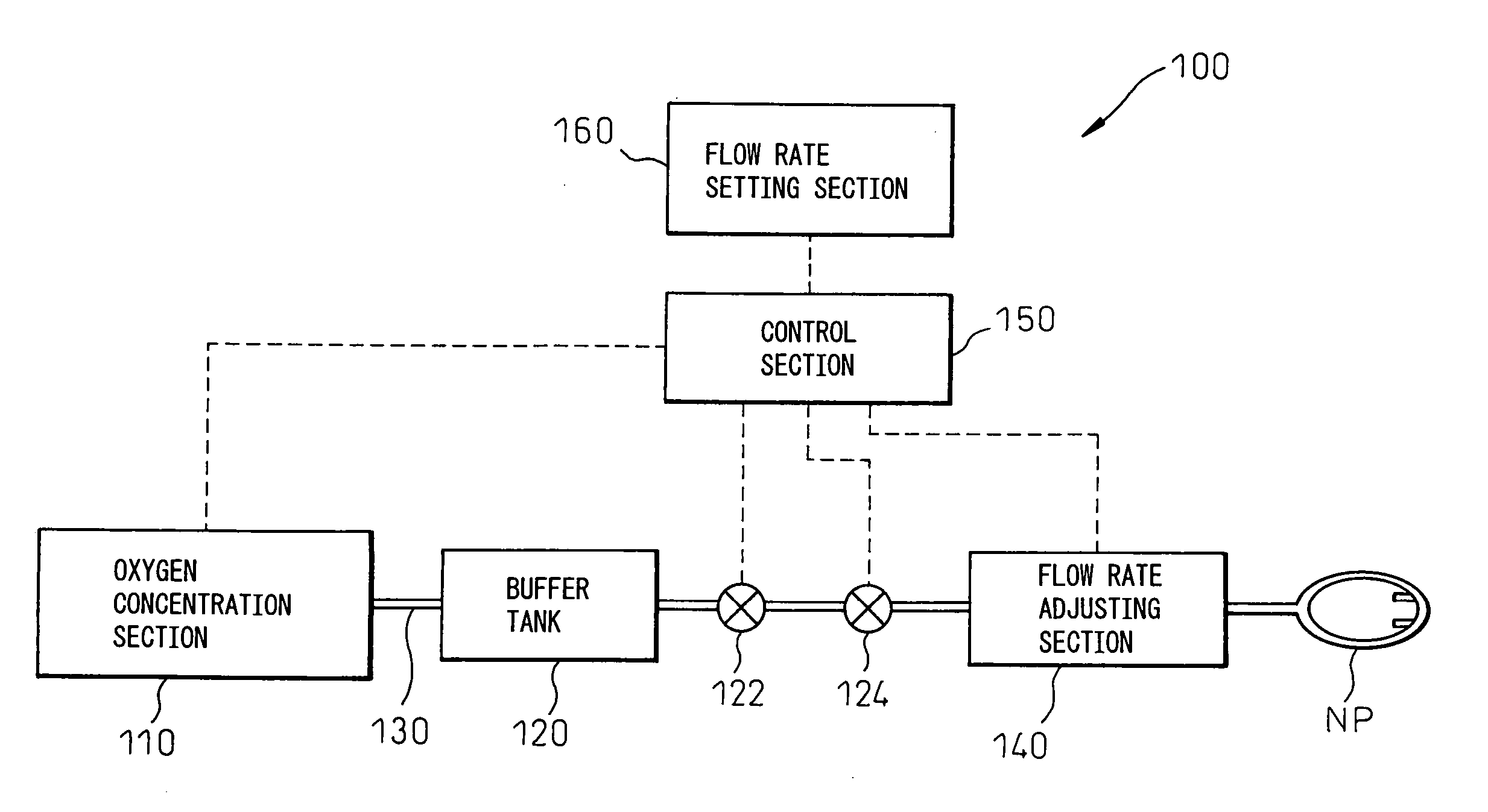
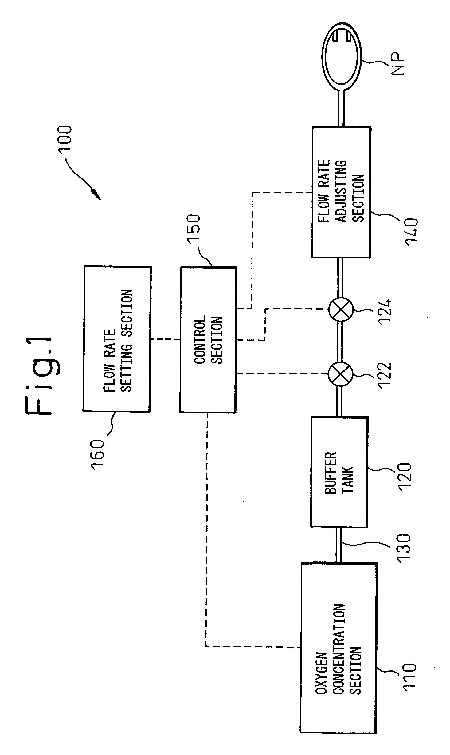
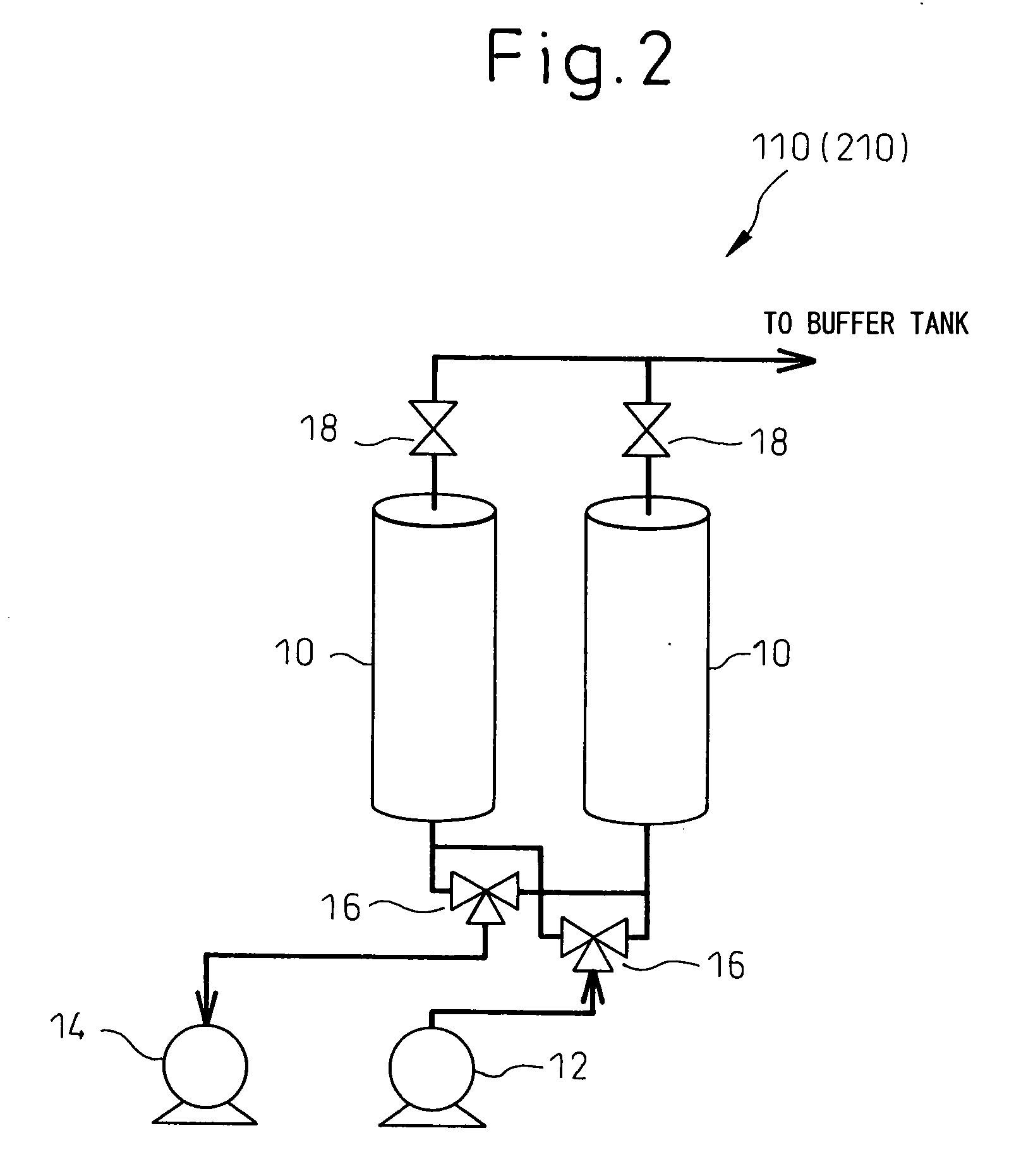
[0054] With reference to FIG. 1, an oxygen concentration apparatus 100 according to a preferred embodiment of the present invention comprises as main components: a pressure swing adsorption type oxygen concentration section 110; a pressure sensor 122; an oxygen concentration sensor 124; a flow rate adjusting section 140; a flow rate setting section 160; and a control section 150 for controlling the effect of the oxygen concentration section 110 and the flow rate adjusting section 140, and the oxygen concentration section 110, the pressure sensor 122, the oxygen concentration sensor 124 and the flow rate adjusting section 140 are arranged along a conduit 130. A buffer tank 120 for temporarily storing oxygen concentrated gas generated in the oxygen concentration section 110 may be provided between the oxygen concentration section 110 and the flow rate adjusting section ...


PUM


Abstract

An oxygen concentration apparatus (300) according to the present invention has: pressure swing adsorption type oxygen concentration means (310); and a control means (350) that controls switching means (316) that switches between intake of pressurized air into an adsorption column (312) and exhaust from the adsorption column. The switching means is controlled based on pressure in oxygen concentrated gas in the conduit measured by pressure measuring means to adjust a cycle of adsorption and regeneration processes of the oxygen concentration means so that pressure at the upstream of flow rate adjusting means (340) can be controlled and, as a result, the need for a mechanical pressure regulating valve, that has been needed conventionally, can be eliminated. Further, there is also shown a gas supply apparatus that comprises ultrasonic type gas concentration and flow rate measuring means that comprises, in turn, two ultrasonic transducers that is disposed in an opposed manner in the conduit through which product gas flows so that a concentration value measured when the product gas output is stopped is determined to be a product gas concentration.

Description

BACKGROUND OF THE INVENTION [0001] 1. Field of the Invention [0002] The present invention relates to a pressure swing adsorption-type oxygen concentration apparatus using an adsorbent that preferentially adsorbs nitrogen rather than oxygen and, in particular, it relates to a medical oxygen-concentration apparatus used in oxygen-inhalation therapy that is a treatment for respiratory diseases. [0003] 2. Description of the Related Art [0004] In recent years, the number of patients that suffer from respiratory diseases such as asthma, pulmonary emphysema, chronic bronchitis and the like has been growing. One of the most effective therapy methods for such respiratory diseases is oxygen inhalation therapy that allows the patient to inhale an oxygen-concentrated gas or oxygen-enriched air. As a source of the oxygen-concentrated gas or the oxygen-enriched air supplied to the patient (referred to as the “oxygen supply source” in this specification), an oxygen concentration apparatus, liquid ...

Claims


Application Information

Patent Timeline
IPC IPC(8): B01D53/02A61M16/00A61M16/06A61M16/10B01D53/04B01D53/053B01J
CPCA61M16/10A61M2016/0027A61M2016/0039B01D53/0423B01D53/053B01D2256/12A61M16/101B01D2259/40005B01D2259/40007B01D2259/402B01D2259/404B01D2259/4533A61M16/0677B01D2257/102G01N29/024G01N29/326A61M2016/0021A61M2016/1025A61M2205/3334A61M2205/3375G01N2291/021G01N2291/02809G01N2291/02836A61M16/202A61M16/107A61M16/085A61M16/203A61M2202/0208A61M2202/03A61M2202/0007
Inventor NAWATA, HIDEOFUJIMOTO, NATOSHIKUROME, KANJIMATSUBARA, SADAKAZU
Owner TEIJIN LTD
Learn More