Oilfield choke with teardrop shaped flow orifices

a technology of oilfield choke and flow orifice, which is applied in the direction of valve operating means/release devices, wellbore/well accessories, sealing/packing, etc., can solve the problems of costly downtime, erosion and corrosion problems of choke valves and other surface equipment, and achieve the effect of reducing the interior erosion, reducing the shear force, and reducing the corrosion and erosion

Active Publication Date: 2021-02-02
ALLEN JACK
View PDF15 Cites 1 Cited by
  • Summary
  • Abstract
  • Description
  • Claims
  • Application Information

AI Technical Summary

Benefits of technology

[0008]One aspect of this invention is to manipulate the shape of the one or more holes disposed in the wall of the cage insert or of the seat carrier. The changing of the shape of these orifices can change the way the fluid flows through the choke valve. Ideally, the manipulation in shape can result in a reduction of shear force and emulsification of the fluid, and also result in a reduction of corrosion and erosion of the surface equipment, notably the choke valve.
[0009]Another aspect of the invention is to present teardrop shaped holes, or orifices, and manipulation of the position of the internal sliding flow control member such that the regulation of the pressure passing through the choke valve is regulated more uniformly thereby reducing erosion of the interior of the choke valve body.

Problems solved by technology

Such conditions often cause the choke valve and other surface equipment to encounter erosion and corrosion problems.
The erosion and corrosion often causes the surface equipment to fail, resulting in costly down-time for the well while the equipment is replaced.

Method used


Image

  • Oilfield choke with teardrop shaped flow orifices
  • Oilfield choke with teardrop shaped flow orifices
  • Oilfield choke with teardrop shaped flow orifices

Examples


Embodiment Construction

[0021]The apparatus disclosed herein can include a manipulation to a current choke valve apparatus or the manufacture of a new choke valve apparatus. Manipulation of an existing choke valve apparatus can include the replacement of one or both of the seat carrier or cage insert.

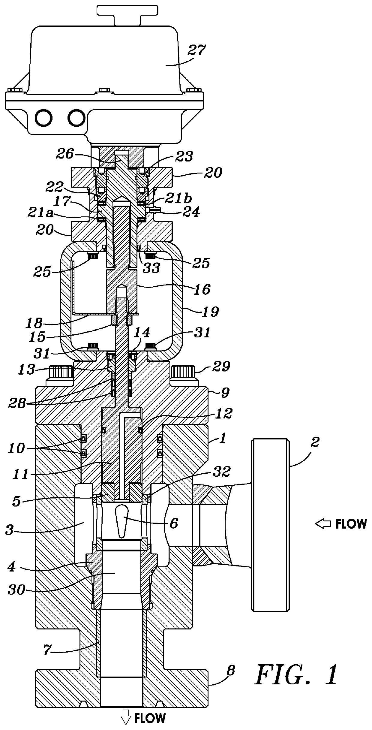
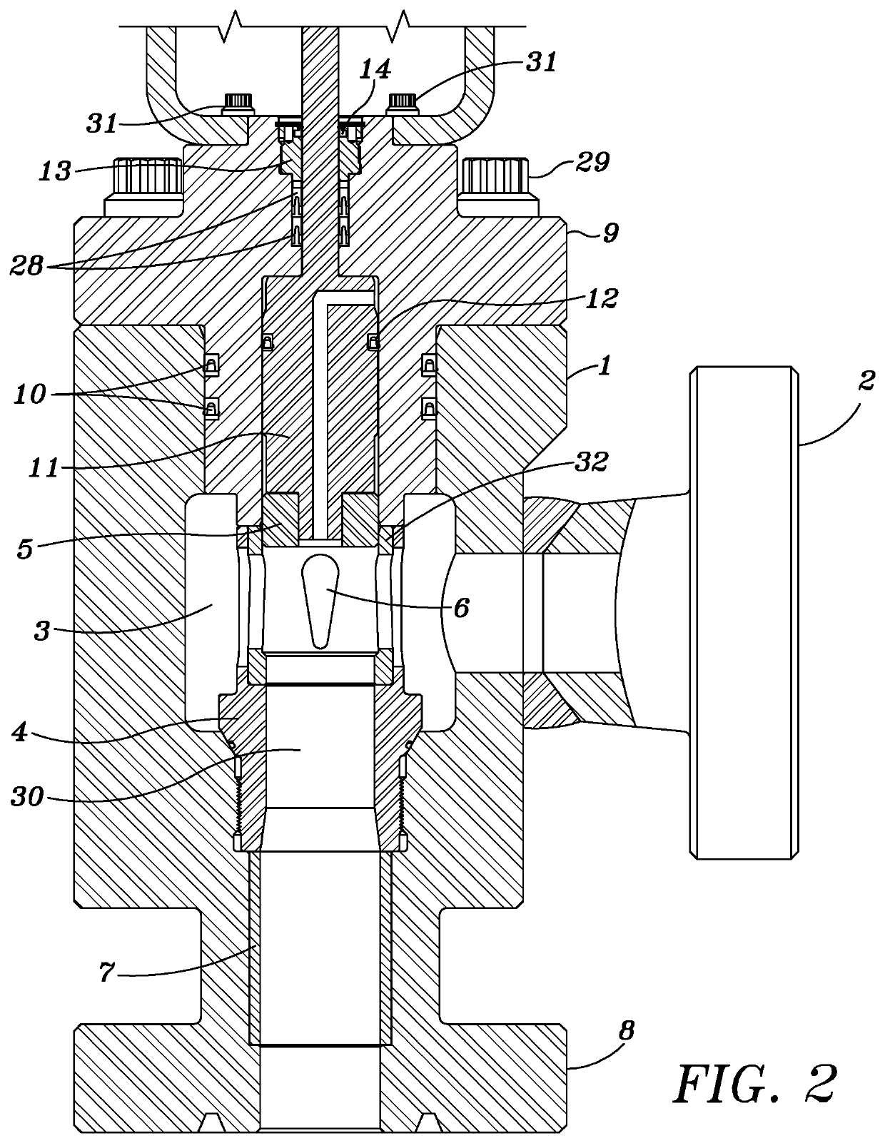
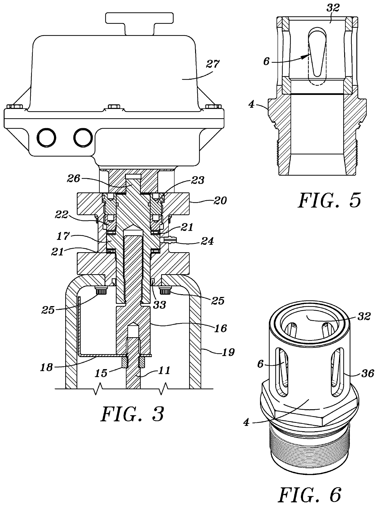
[0022]FIG. 1 depicts a cross-sectional view of a choke valve assembly. FIG. 2 depicts a cross-sectional close-up view of the bottom portion of the choke valve assembly of FIG. 1 and FIG. 3 depicts a cross-sectional close-up view of the top portion of the choke valve assembly of FIG. 1.

[0023]The choke valve assembly can include a choke valve body 1 comprising an inlet 2, an internal chamber 3, and an outlet 8. The internal chamber 3 can house a choke valve seat carrier 4 with a cage 32 about a top portion and an abrasion resistant sleeve 7 extending there below or in a bottom portion. In other words, the abrasion resistant sleeve 7 can be disposed in the choke valve body 1 below the seat carrier 4 and above the...


PUM


Abstract

A cage for a choke valve assembly and method for using the same is provided. The cage includes one or more teardrop shaped orifices for the manipulation of fluid flow through the choke valve assembly.

Description

PRIORITYClaim Priority to Provisional Patent Application[0001]This application is a non-provisional utility patent application claiming priority to previously filed provisional patent application titled “Automated or Manually Operated Oilfield Choke with Teardrop Shaped Flow Orifices” and having application No. 62 / 606,500 and filed on Dec. 27, 2017.BACKGROUND[0002]The present invention is directed to a choke valve seat with a plurality of teardrop shaped flow orifices to regulate flow passing through the choke valve.DESCRIPTION OF RELATED ART[0003]The control of flow is a requirement to obtain safe, flexible and reliable operations of high-pressure oilfield production systems. A choke valve is a type of control valve, mostly used in oil and gas production wells to control the flow of well fluids being produced. Production fluids typically include crude oil, water, and natural gas.[0004]Choke valve assemblies allow for the control of production fluids exiting the well. They often inc...

Claims


Application Information

Patent Timeline
Patent Type & Authority Patents(United States)
IPC IPC(8): E21B34/02F16K3/24F16K3/34F16K31/50
CPCE21B34/02F16K3/24F16K3/246F16K3/34F16K31/508E21B34/025
Inventor ALLEN, JACK
Owner ALLEN JACK
Why Eureka
Try Eureka