
Optimization of superstructures and/or mesostructures in dental prostheses

a technology of dental prostheses and superstructures, applied in dental prostheses, medical science, dentistry, etc., can solve the problems of not being able or advisable to attach the dental prosthesis directly to the abutment, not being able to accurately calculate the statics of the mesostructure, and largely disregarded or at least not sufficiently taken into account in the biomechanical properties of the jawbone. , to achieve the effect of minimizing the flexibility of the mesostructure, minimizing

Active Publication Date: 2021-01-19
CADFEM INT GMBH
View PDF21 Cites 0 Cited by
  • Summary
  • Abstract
  • Description
  • Claims
  • Application Information

AI Technical Summary

Benefits of technology

This approach ensures that only necessary structural elements are used, minimizing material and weight while ensuring stability and aesthetics, optimizing the distribution of forces and preventing overloading of implants.

Problems solved by technology

In many cases, in particular, in the case of dental prostheses requiring a larger number of abutments (tooth stumps, dental implants or posts and cores) and / or are to replace a larger number of missing teeth, it is not possible or advisable to attach the dental prosthesis directly to the abutments.
However, the respective individual biomechanical properties of the jawbone are largely disregarded or at least not sufficiently taken into consideration, and in the majority of cases the statics of the mesostructure are not calculated accurately either.
In particular, the result may be that implants are used that do not absorb any load, i.e. implants upon which no force at all or only very little force is exerted during chewing, when the dental prosthesis is inserted, and therefore are actually considered to be superfluous.
This leads to additional costs and may also have an adverse effect from an aesthetic point of view.

Method used


Image

  • Optimization of superstructures and/or mesostructures in dental prostheses
  • Optimization of superstructures and/or mesostructures in dental prostheses

Examples


Embodiment Construction

[0056]The following description of the preferred embodiment(s) is merely exemplary in nature and is in no way intended to limit the invention, its application, or uses.

[0057]First of all, the use of the terms “superstructure” and “mesostructure” is to be explained in more detail.

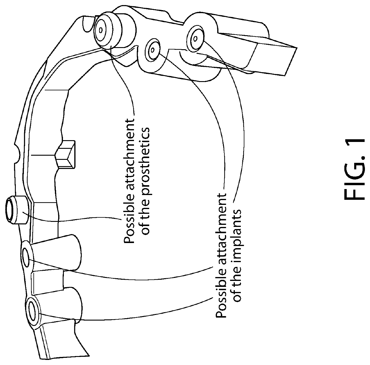
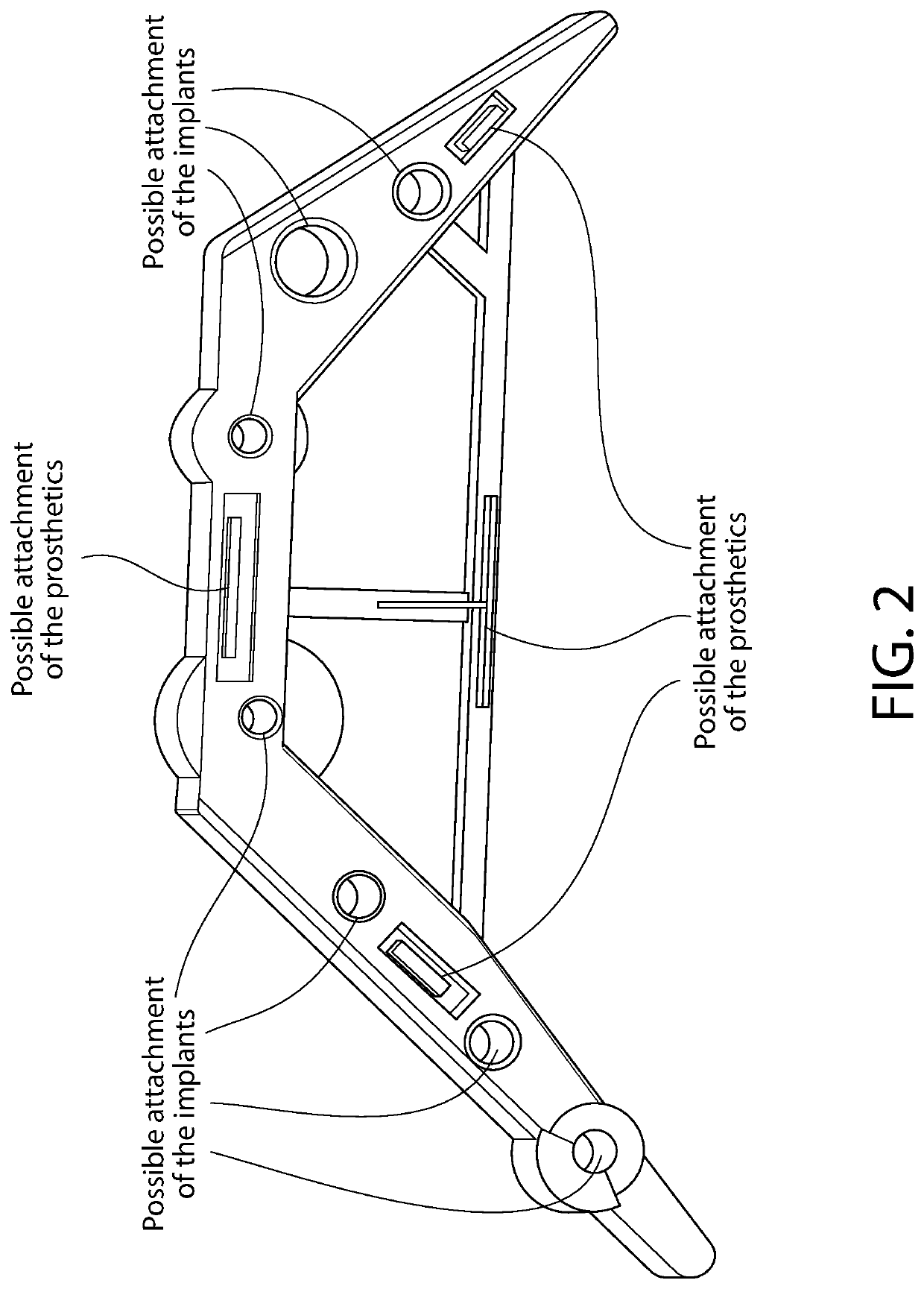
[0058]A superstructure usually refers to all those parts that are placed onto or attached to the implants or abutments, respectively. A mesostructure refers to an intermediate link, e.g. a web, attachment bars, or special design which is arranged between the implants and the prosthesis or the denture. Thus, the term superstructure covers, for example, both the mesostructure and the prosthesis. However, such a distinction is not always made very clearly, so that sometimes only the intermediate link, for example, a web or attachment bars are referred to as superstructure. In addition, the English language does not have an exact equivalent of the German term “Mesiokonstruktion” [mesostructure]. Therefore, it ma...


PUM


Abstract

A method and device for developing a geometry of a superstructure and / or mesostructure for dental prostheses. According to one aspect of the invention a method of developing a geometry of a mesostructure for a dental prosthesis includes the following steps: receiving first 3D data defining a 3D installation space for a mesostructure, receiving second 3D data defining possible positions for attaching the mesostructure, receiving third 3D data defining possible positions or regions for attaching the dental prosthesis to the mesostructure, and developing an optimized geometry of the mesostructure by means of an optimization technique, wherein starting from the 3D installation space the possible positions for attaching the mesostructure and the possible positions or regions for attaching the dental prosthesis to the mesostructure, the geometry of the mesostructure is optimized by means of applying the physical laws.

Description

CROSS-REFERENCE TO RELATED APPLICATIONS[0001]The present application claims priority under 35 § 119 to German Patent Application No. 102016003084.4, filed on Mar. 14, 2016, the entirety of which is incorporated herein by reference.FIELD OF THE INVENTION[0002]The invention relates to a method and a device for developing a geometry of a superstructure and / or mesostructure in dental prostheses. Furthermore, the invention relates to a computer-readable medium including program code instructions executable by a computer for performing such a method, as well as a computer program including program code means for performing such a method when the program is executed on a computer. In addition, the invention relates to a superstructure and / or mesostructure which is manufactured by using the data generated in the method according to the invention.BACKGROUND OF THE INVENTION[0003]A distinction is made between e.g. removable dental prostheses and fixed dental prostheses.[0004]Both types of den...

Claims


Application Information

Patent Timeline
Patent Type & Authority Patents(United States)
IPC IPC(8): A61C13/01A61C13/00A61C8/00
CPCA61C13/0004A61C8/005A61C8/0027
Inventor MULLER, CHRISTOPHBONITZ, LARS
Owner CADFEM INT GMBH
Learn More