
Flood control system

Active Publication Date: 2020-11-24
BURKETT GLENN
View PDF27 Cites 0 Cited by
  • Summary
  • Abstract
  • Description
  • Claims
  • Application Information

AI Technical Summary

Benefits of technology

The present invention is a floodwater control system that can be quickly deployed to prevent floodwaters from entering a desired area. The system includes modular receptacles that can be folded for easy transportation and erected in a second position to inhibit floodwaters. Each receptacle has a interior volume and a liner that can be closed or open. The receptacles can be secured together using locking pins. The invention has technical effects such as rapid deployment, easy folding, erection, and the use of liners to prevent floodwaters from entering desired areas.

Problems solved by technology

Further desirable properties such as those near rivers and lakes are prone to rapid flooding in the event of either a natural disaster or a catastrophic failure of structures such as but not limited to a dam.
One issue with existing flood control is the capacity limitation of structures such as but not limited to canals and the inability to rapidly deploy a temporary structure that is operable to inhibit water egress into a certain area.
In the event of natural disasters such as but not limited to hurricanes, those municipalities that have canal systems configured to control excess water and the direction thereof often struggle with water control ensuing the capacity of the canals being reached.
Additionally, temporary structures utilized for controlling floodwaters can not quickly be deployed and require significant manpower to install.
Conventional technology such as sand bags have proven to provide some relief but sandbags require significant manpower to fill and deploy.
Further, sandbags are small and as such they are unable to protect larger areas and typically are utilized to circumferentially surround a structure such as but not limited to a house.

Method used


Image

  • Flood control system
  • Flood control system
  • Flood control system

Examples


Embodiment Construction

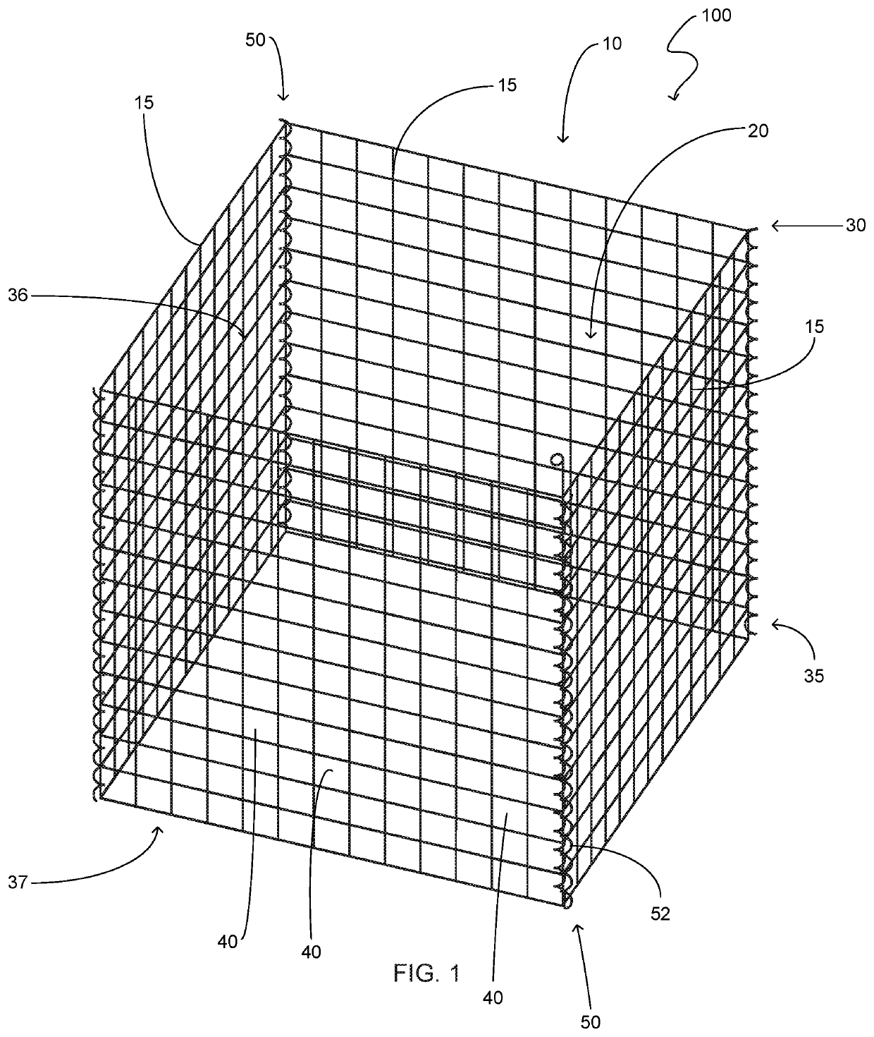
[0022]Referring now to the drawings submitted herewith, wherein various elements depicted therein are not necessarily drawn to scale and wherein through the views and figures like elements are referenced with identical reference numerals, there is illustrated an flood control system 100 constructed according to the principles of the present invention.

[0023]An embodiment of the present invention is discussed herein with reference to the figures submitted herewith. Those skilled in the art will understand that the detailed description herein with respect to these figures is for explanatory purposes and that it is contemplated within the scope of the present invention that alternative embodiments are plausible. By way of example but not by way of limitation, those having skill in the art in light of the present teachings of the present invention will recognize a plurality of alternate and suitable approaches dependent upon the needs of the particular application to implement the functi...


PUM


Abstract

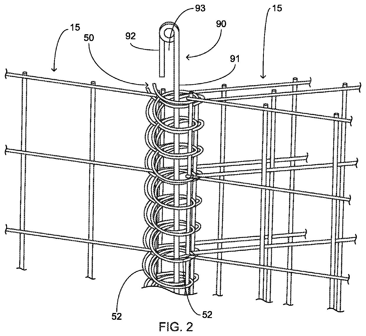
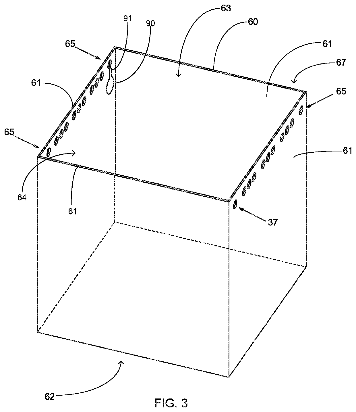
A flood control system that is configured to be deployed so as to control floodwaters wherein the flood control system is provided in multi-cell configurations of modular receptacles. The flood control system includes a plurality of modular receptacles having four walls wherein the four walls are movably coupled so as to transition intermediate a folded position and a deployed position. The walls of the flood control system include a plurality of apertures and corner structures that are helical coil in shape. A locking pin is provided to be operably coupled intermediate modular receptacles so as to provide a mechanical connection therebetween. A liner is disposed within the interior volume of the modular receptacles and is mateable shaped therewith. A lid member is further included and is operable to cover the plurality of modular receptacles. The lid member further includes locking aperture rows so as to inhibit access.

Description

CROSS REFERENCE TO RELATED APPLICATIONS[0001]This application is a continuation-in-part of U.S. patent application Ser. No. 15 / 821,232 filed, Nov. 22, 2017, entitled, Flood Control System, now abandoned, which is hereby incorporated for reference.FIELD OF THE INVENTION[0002]The present invention relates generally to flood control, more specifically but not by way of limitation a flood control system configured to assist municipalities and the like to quickly deploy flood control in desired areas wherein the flood control system includes modular receptacles configured for rapid deployment.BACKGROUND[0003]As the population density increase in various area, the flood plains in these are now being built on in greater density. In years past, municipalities had identified flood plains and the availability of land was such that development in the flood plain areas was minimal. As commercial and residential development has expanded over the last several decades, the once undeveloped floodpl...

Claims


Application Information

Patent Timeline
IPC IPC(8): E02B3/10E02B7/00E02D29/02
CPCE02B7/005E02B3/108E02D29/0208
Inventor BURKETT, GLENN
Owner BURKETT GLENN
Learn More