
Power transmission apparatus for vehicle

a technology for power transmission and vehicles, applied in the direction of gearing details, gearing, transportation and packaging, etc., can solve the problems of easy deterioration of installation, production cost, weight and/or power flow efficiency, hard competition in enhancing fuel consumption of vehicles, etc., to improve power delivery performance and fuel consumption, improve installationability, and facilitate optimization

Active Publication Date: 2020-11-17
HYUNDAI MOTOR CO LTD +1
View PDF1 Cites 3 Cited by
  • Summary
  • Abstract
  • Description
  • Claims
  • Application Information

AI Technical Summary

Benefits of technology

The power transmission apparatus for vehicles described in this patent offers a wide range of shifting stages, allowing for easy optimization for different vehicle specifications. It also uses a simple four-speed dual-clutch transmission (DCT) structure to improve power delivery performance and fuel efficiency. This results in a smaller, more manageable transmission that is easier to install.

Problems solved by technology

Research on realizing more shifting stages of an automatic transmission are undertaken to achieve enhancement of fuel consumption and better drivability, and recently, increase of oil price is triggering a hard competition in enhancing fuel consumption of a vehicle.
To achieve more shifting stages for an automatic transmission, the number of parts is typically increased, which may deteriorate installability, production cost, weight and / or power flow efficiency.
An automatic transmission of eight or more shifting stages typically may include three to four planetary gear sets and five to seven engagement elements (friction elements), and may easily become lengthy, deteriorating installability.
However, such an arrangement may not be widely applicable, and using dog clutches may easily deteriorate shift-feel.

Method used


Image

  • Power transmission apparatus for vehicle
  • Power transmission apparatus for vehicle
  • Power transmission apparatus for vehicle

Examples


Embodiment Construction

[0038]Reference will now be made in detail to various embodiments of the present invention(s), examples of which are illustrated in the accompanying drawings and described below. While the present invention(s) will be described in conjunction with exemplary embodiments of the present invention, it will be understood that the present description is not intended to limit the present invention(s) to those exemplary embodiments. On the other hand, the present invention(s) is / are intended to cover not only the exemplary embodiments of the present invention, but also various alternatives, modifications, equivalents and other embodiments, which may be included within the spirit and scope of the present invention as defined by the appended claims.

[0039]In the following detailed description, only certain exemplary embodiments of the present invention have been shown and described, simply by way of illustration. As those skilled in the art would realize, the described embodiments may be modif...


PUM


Abstract

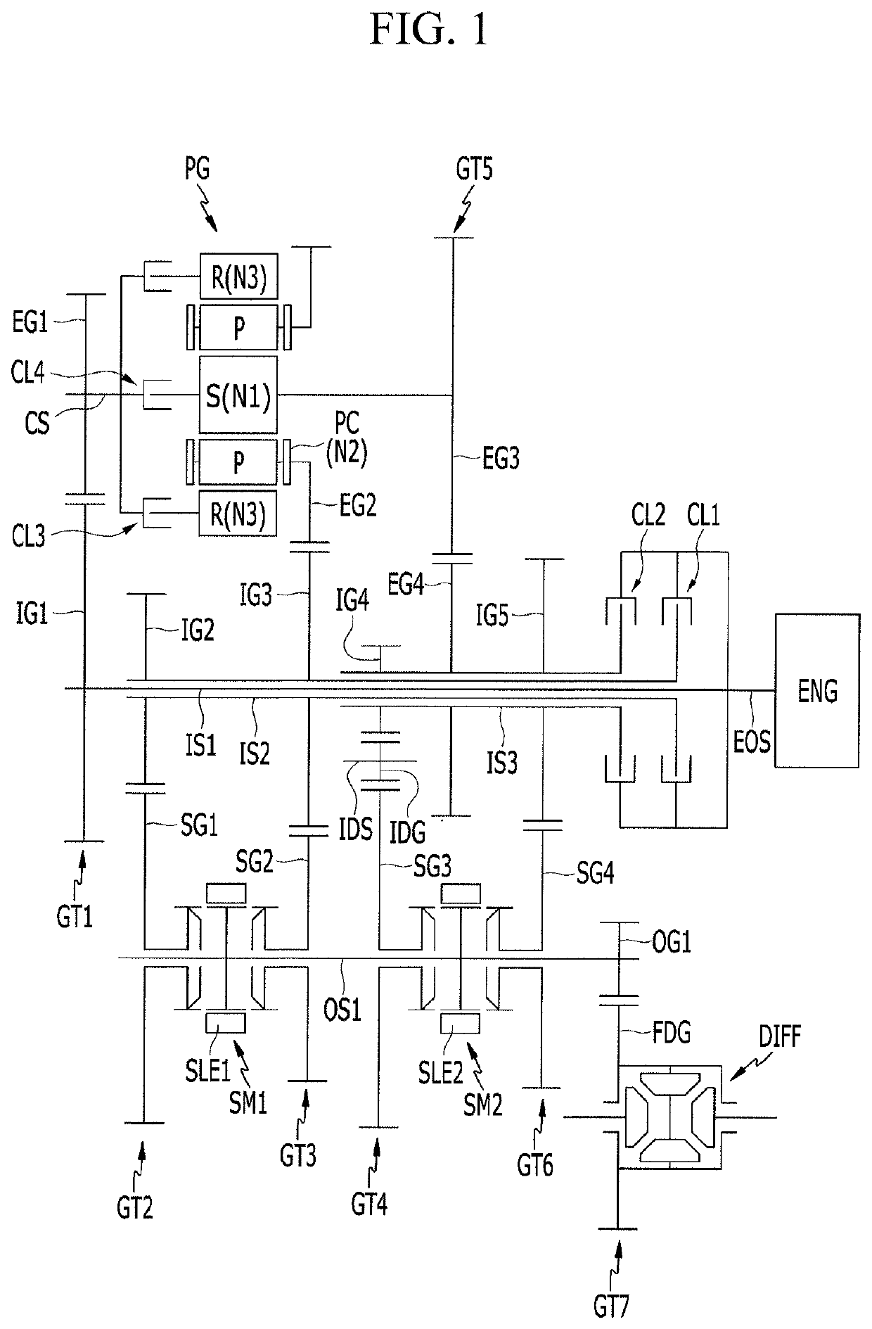
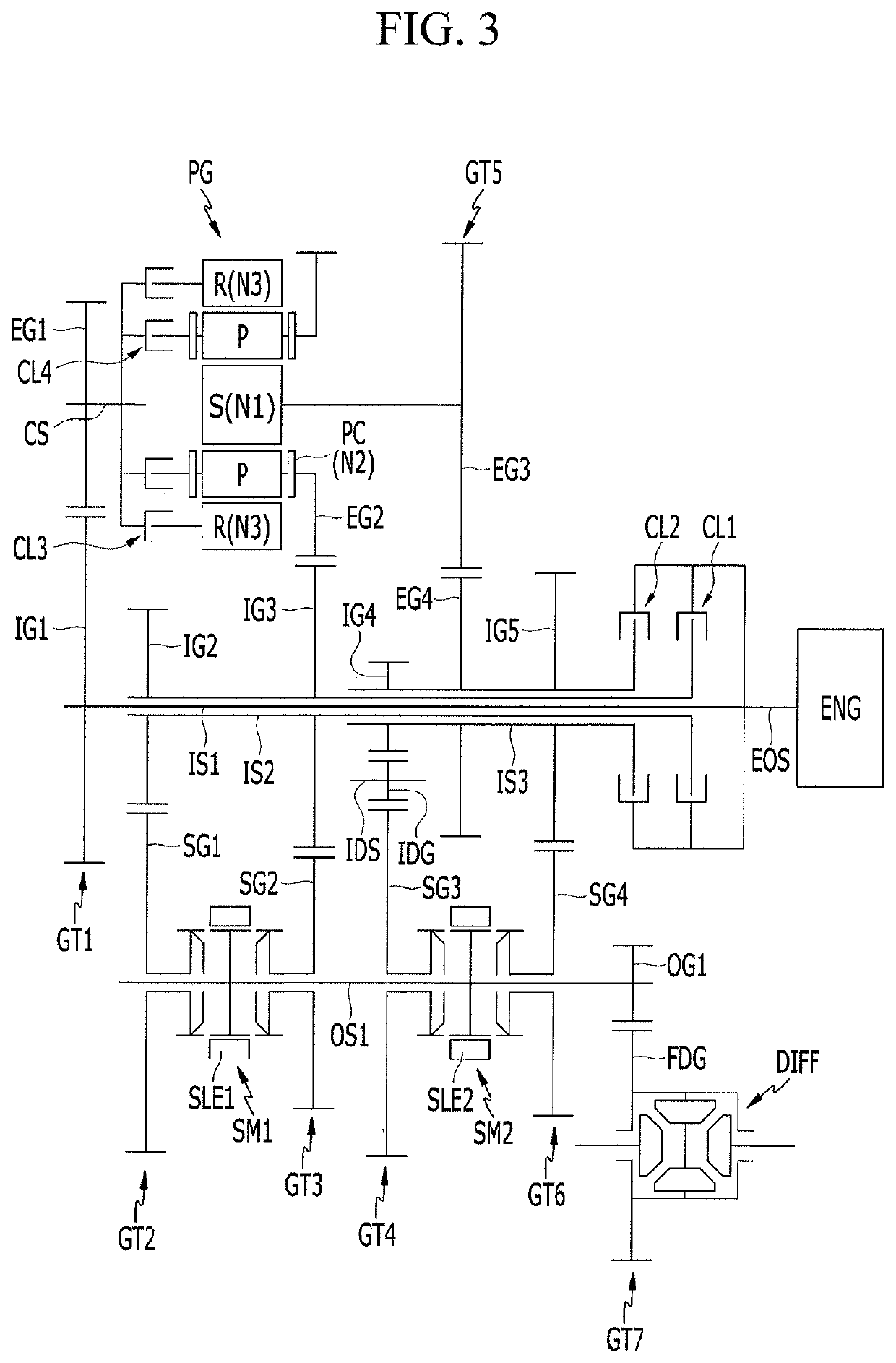
A transmission may include a first input shaft, a second input shaft external and selectively connectable to the first input shaft, a third input shaft external to the second input shaft and selectively connectable to the first input shaft, an intermediate shaft, an idle shaft, and an output shaft, a planetary gear set mounted on the intermediate shaft and having first to third elements where the third element and one the first and second elements are selectively connectable to the intermediate shaft and the first and second elements are connected to the third and second input shafts, a plurality of gear sets allowing torque flows between the various shafts and the planetary gear set, first and second synchronizers on the output shaft, receiving torques from the input shafts, and selectively transmitting the received torque to the output shaft, and four clutches.

Description

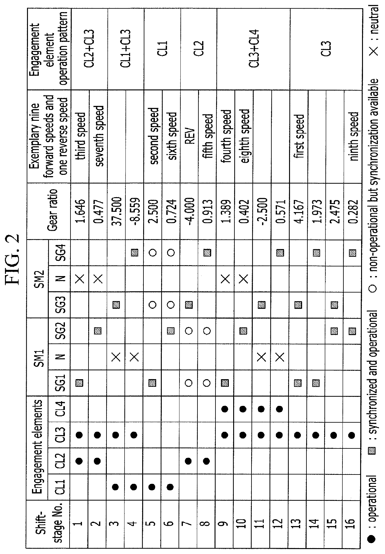
CROSS-REFERENCE TO RELATED APPLICATION[0001]The present application claims priority to Korean Patent Application No. 10-2019-0065338 filed on Jun. 3, 2019, the entire contents of which is incorporated herein for all purposes by this reference.BACKGROUND OF THE INVENTIONField of the Invention[0002]The present invention relates to a power transmission apparatus for a vehicle.Description of Related Art[0003]Research on realizing more shifting stages of an automatic transmission are undertaken to achieve enhancement of fuel consumption and better drivability, and recently, increase of oil price is triggering a hard competition in enhancing fuel consumption of a vehicle.[0004]In the present sense, research on an engine has been undertaken to achieve weight reduction and to enhance fuel consumption by so-called downsizing research on an automatic transmission has been performed to simultaneously provide better drivability and fuel consumption by achieving more shifting stages.[0005]To ach...

Claims


Application Information

Patent Timeline
IPC IPC(8): F16H37/08F16H37/04
CPCF16H37/046F16H37/0826F16H2200/2064F16H2037/048F16H2037/047F16H2200/0078F16H2200/0065F16H2200/2005F16H2200/2041F16H3/006F16H2003/0826F16H37/04F16H3/44F16H3/093F16H3/085F16H3/12F16H2200/0043F16H57/08F16H2702/02
Inventor KIM, CHON OKHWANG, SEONG WOOKEO, SOONKICHAE, MINHOKWON, SUN SUNGSHIN, YONG UK
Owner HYUNDAI MOTOR CO LTD
Learn More