
Display device, method for controlling display device, program, recording medium, and moving body equipped with display device

a display device and display technology, applied in the field of display devices, can solve the problems of increasing the amount of deviation of the reference position, the possibility of occurrence of variations in the distance between the user's (driver's) eyes and the virtual image, and the accumulation of reference positions. the effect of reducing the variation in the distance from the user's eyes

Active Publication Date: 2020-10-27
PANASONIC INTELLECTUAL PROPERTY MANAGEMENT CO LTD
View PDF27 Cites 0 Cited by
  • Summary
  • Abstract
  • Description
  • Claims
  • Application Information

AI Technical Summary

Benefits of technology

[0005]In the display device described above, a position that serves as a reference (a reference position) is decided as for a position of the screen, and the screen is moved relative to this reference position. Accordingly, in a case where the reference position of the screen is displaced, there is a possibility of occurrence of variations in distance between user's (driver's) eyes and a virtual image even in a case where the display device displays a same virtual image. In particular, in a case where the reference position is deviated every time the screen is moved, an amount of deviation of the reference position is accumulated. This may undesirably increase the amount of deviation of the reference position, thereby increasing variations in distance between user's eyes and a virtual image.
[0006]The present disclosure provides a display device that can reduce a variation in distance between user's eyes and a virtual image, a method for controlling the display device, a program, a recording medium, and a moving body equipped with the display device.
[0011]The present disclosure has an advantage of reducing a variation in distance from user's eyes to a virtual image.

Problems solved by technology

Accordingly, in a case where the reference position of the screen is displaced, there is a possibility of occurrence of variations in distance between user's (driver's) eyes and a virtual image even in a case where the display device displays a same virtual image.
In particular, in a case where the reference position is deviated every time the screen is moved, an amount of deviation of the reference position is accumulated.
This may undesirably increase the amount of deviation of the reference position, thereby increasing variations in distance between user's eyes and a virtual image.

Method used


Image

  • Display device, method for controlling display device, program, recording medium, and moving body equipped with display device
  • Display device, method for controlling display device, program, recording medium, and moving body equipped with display device
  • Display device, method for controlling display device, program, recording medium, and moving body equipped with display device

Examples


first exemplary embodiment

[0030](1) Outline

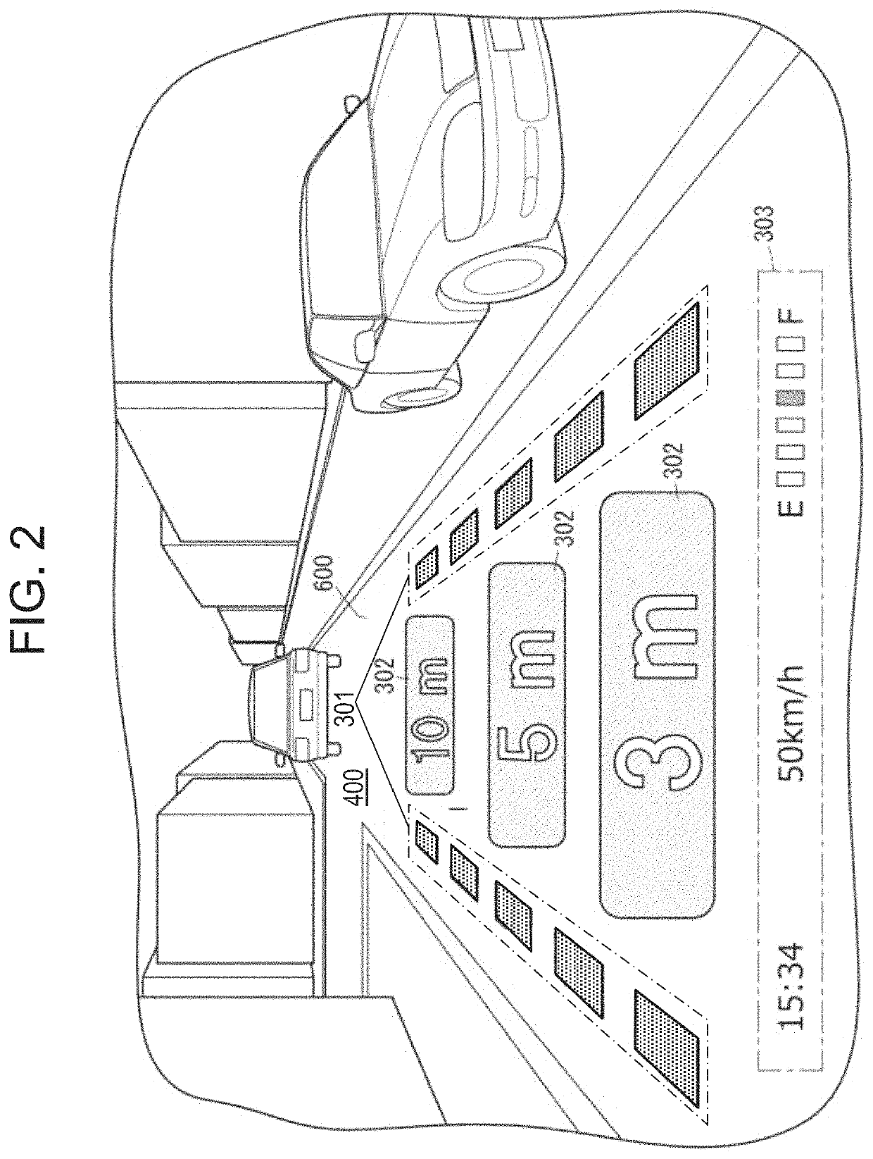
[0031]As illustrated in FIG. 1, display device 10 according to the present exemplary embodiment is, for example, a head-up display (HUD) for use in vehicle 100 that is a moving body. FIG. 1 is a conceptual diagram of vehicle 100 having display device 10. Vehicle 100 has main body 104, moving body driving unit 106 that moves main body 104, display device 10 mounted in main body 104, and windshield 101 fixed to main body 104. Moving body driving unit 106 includes drive source 108 such as an engine or a motor and drive wheels 110 driven by drive source 108.

[0032]Display device 10 is installed in a cabin of vehicle 100 so as to project an image onto windshield 101 of vehicle 100 from below. In the example of FIG. 1, display device 10 is disposed in dashboard 102 below windshield 101. When an image is projected from display device 10 onto windshield 101, user 200 visually recognizes the image reflected by windshield 101 serving as a reflective member.

[0033]According to s...

second exemplary embodiment

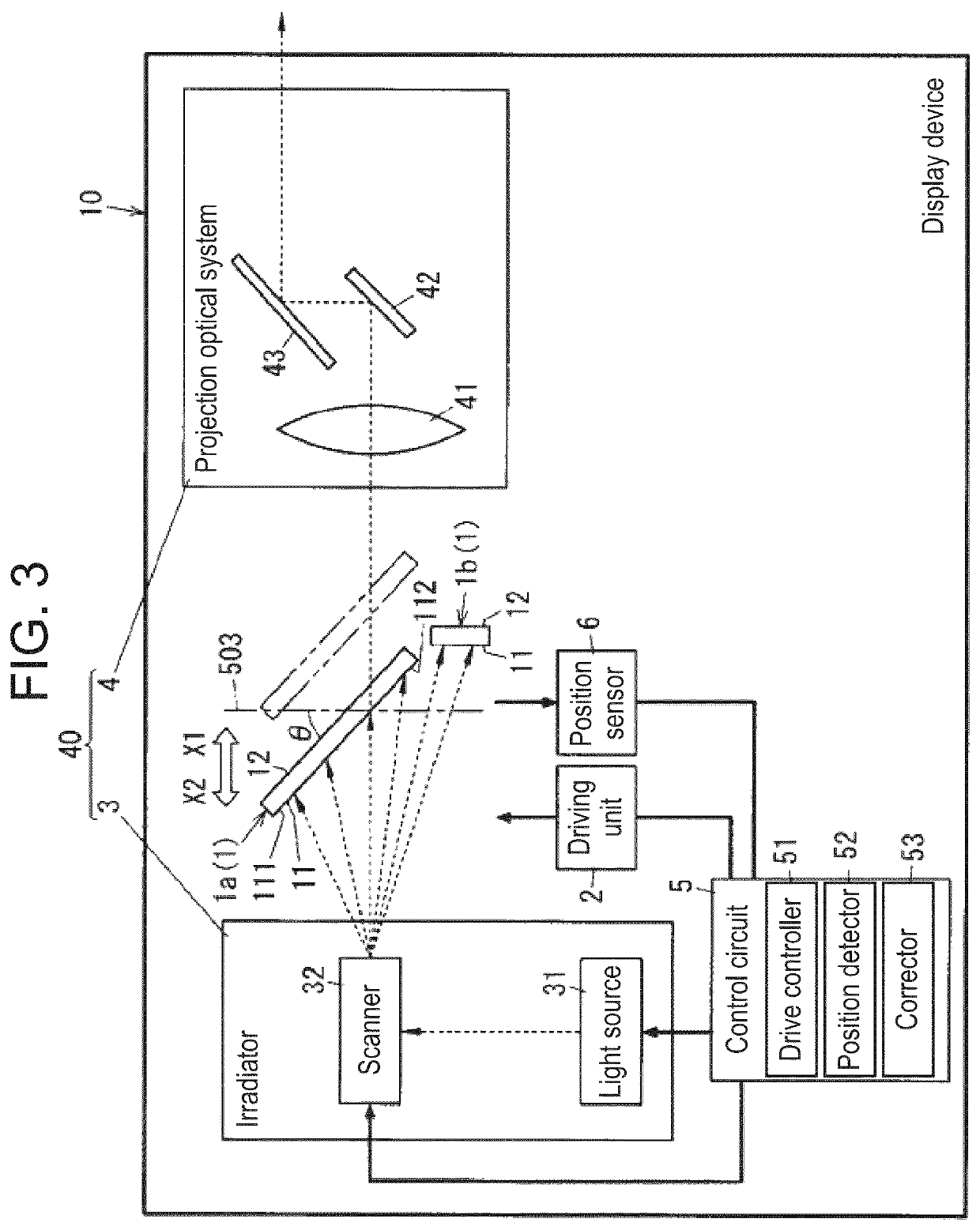
[0147]According to display device 10 according to a second exemplary embodiment of the present disclosure, position detector 52 executes position detection processing while using, as a trigger, movement of movable screen 1a by drive controller 51 in a movable display period. In this respect, display device 10 according to the second exemplary embodiment is different from display device 10 according to the first exemplary embodiment. A basic configuration in the present exemplary embodiment is similar to the configuration of FIG. 3 referred to in the first exemplary embodiment. Hereinafter, constituent elements identical to those of the first exemplary embodiment are given identical reference signs and explanations thereof will be omitted.

[0148]In the present exemplary embodiment, a movable display period in which movable screen 1a is irradiated with light from projector 40 is intermittently set as in the first exemplary embodiment. That is, a movable display period in which movable ...

third exemplary embodiment

[0162]FIG. 12 is a conceptual diagram illustrating a configuration of display device 10A according to a third exemplary embodiment of the present disclosure. Display device 10A is different from display device 10 according to the first exemplary embodiment in that display device 10A has only movable screen 1a as screen 1. Hereinafter, constituent elements identical to those of the first exemplary embodiment are given identical reference signs and explanations thereof will be omitted.

[0163]That is, in the present exemplary embodiment, fixed screen 1b illustrated in FIG. 3 is omitted, and projector 40 (projection optical system 4 and irradiator 3) performs drawing only on movable screen 1a. That is, projector 40 always selects movable screen 1a as a target screen and performs drawing on movable screen 1a by irradiating movable screen 1a with light used for scanning movable screen 1a. Then, projector 40 projects virtual image 300 (first virtual image 301 or second virtual image 302) on...


PUM


Abstract

A display device has a movable screen that is movable in a movement direction, a drive controller, a projector, and a position detector. The drive controller moves the movable screen relative to a reference position set at a prescribed position in a movement range of the movable screen. The projector performs drawing on the movable screen by irradiating the movable screen with light used for scanning the movable screen and projects a virtual image onto a target space based on light that passes through the movable screen. The position detector executes position detection processing for detecting that the movable screen is located at a detection position set in relation to the prescribed position. The position detector moves the movable screen and executes the position detection processing in a non-display period in which the movable screen is not irradiated with light from the projector.

Description

CROSS-REFERENCE TO RELATED APPLICATIONS[0001]This application is a continuation application of the PCT International Application No. PCT / JP2018 / 004961 filed on Feb. 14, 2018, which claims the benefit of foreign priority of Japanese patent application No. 2017-037682 filed on Feb. 28, 2017 and Japanese patent application No. 2017-037683 filed on Feb. 28, 2017, the contents all of which are incorporated herein by reference.BACKGROUND1. Technical Field[0002]The present disclosure generally relates to a display device, a method for controlling the display device, a program, a recording medium, and a moving body equipped with the display device, and more specifically relates to a display device that projects a virtual image onto a target space by using light that passes through a screen, a method for controlling the display device, a program, a recording medium, and a moving body equipped with the display device.2. Description of the Related Art[0003]Conventionally, a head-up display dev...

Claims


Application Information

Patent Timeline
Patent Type & Authority Patents(United States)
IPC IPC(8): H04N9/31G03B21/14B60K37/02
CPCH04N9/3185G03B21/142B60K37/02B60K2370/1529B60K35/00B60K2370/149B60K2370/177B60K2370/23B60K2370/334G02B26/10G02B27/01G09G3/02H04N9/3129H04N9/317
Inventor MINO, YOSHITERUKUBOTA, KOSUKEOGATA, MASAHITOYAMAMOTO, YUTA
Owner PANASONIC INTELLECTUAL PROPERTY MANAGEMENT CO LTD
Learn More