
Refrigeration cycle apparatus

a cycle apparatus and refrigeration technology, applied in lighting and heating apparatus, heating types, instruments, etc., can solve the problems of inability to provide a sufficient degree of discharge superheat, inability to sufficiently reduce the airflow rate of outdoor fans, and inability to readily rise the temperature of the compressor shell, so as to prevent the reduction of the operation efficiency of the compressor and reduce the airflow rate. , the effect of sufficient discharge superhea

Active Publication Date: 2020-10-13
MITSUBISHI ELECTRIC CORP
View PDF26 Cites 0 Cited by
  • Summary
  • Abstract
  • Description
  • Claims
  • Application Information

AI Technical Summary

Benefits of technology

The present invention is related to a refrigeration cycle apparatus which can efficiently cool the air conditioning system while maintaining the operation efficiency of the compressor. The technical effect of this invention is achieved through intermittent operation of the outdoor fan, which reduces the airflow rate to an optimum value, preventing decreases in the operation efficiency of the compressor and providing a sufficient degree of discharge superheat. This allows the apparatus to achieve efficient cooling without sacrificing performance.

Problems solved by technology

Under such a control, the high-side pressure (condenser pressure) decreases, and the continued intermittent operation also means that the compressor shell temperature does not readily rise.
In some instances, this makes it impossible to provide a sufficient degree of discharge superheat, which is the difference between the compressor shell temperature and the saturation temperature that is calculated from the condenser pressure.
In some instances, due to restrictions on the lower limit rotation speed at which the outdoor fan can be used, it may not be possible to sufficiently reduce the airflow rate of the outdoor fan.

Method used


Image

  • Refrigeration cycle apparatus
  • Refrigeration cycle apparatus
  • Refrigeration cycle apparatus

Examples


embodiment 1

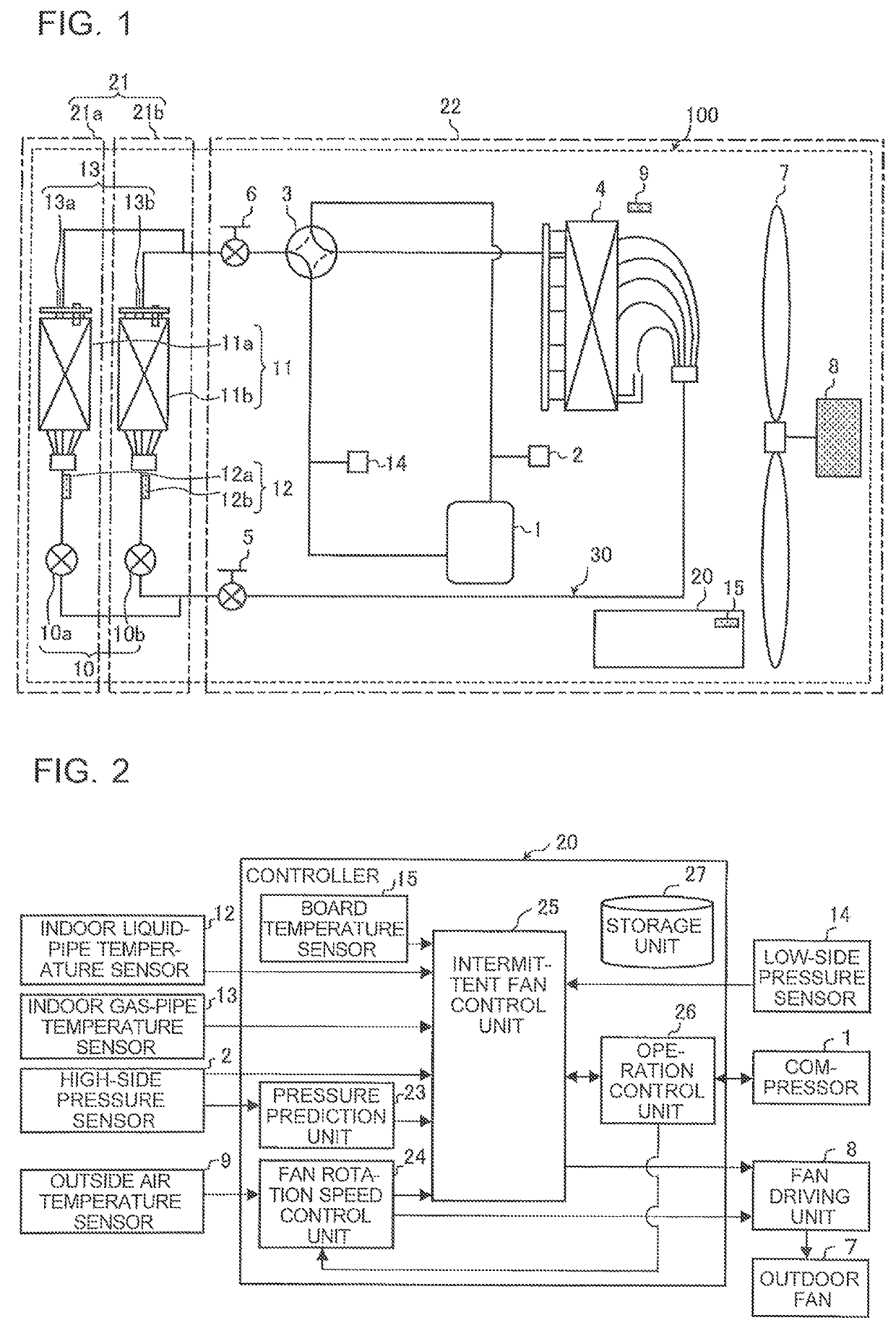
[0018]FIG. 1 illustrates the circulation path of refrigerant in an air-conditioning apparatus equipped with a refrigeration cycle apparatus 100 according to Embodiment 1 of the present invention. As illustrated in FIG. 1, the air-conditioning apparatus includes an indoor unit 21 and an outdoor unit 22.

[0019]The outdoor unit 22 includes a compressor 1, a flow switching device 3, an outdoor heat exchanger 4, a first stationary valve 5, and a second stationary valve 6 that are connected by a refrigerant pipe. The compressor 1 sucks in refrigerant, compresses the sucked refrigerant into a high-temperature, high-pressure state, and transports the resulting refrigerant to a refrigerant circuit 30. The flow switching device 3 is disposed downstream of the compressor 1 to switch the flows of refrigerant between heating operation mode and cooling operation mode. The outdoor heat exchanger 4 performs heat exchange between air and refrigerant. The outdoor heat exchanger 4 acts as a condenser i...

embodiment 2

[0058]The refrigeration cycle apparatus 100 according to Embodiment 2 is of the same configuration as that in Embodiment 1, and included in an air-conditioning apparatus configured in the same manner as in Embodiment 1. It is also assumed that the configuration of the refrigeration cycle apparatus 100 according to Embodiment 2 is the same as that illustrated in FIGS. 1 to 3. In Embodiment 1, the controller 20 is configured to change the ON time Ton at predetermined intervals of time to provide a target degree of discharge superheat. By contrast, in Embodiment 2, the controller 20 is configured to change the OFF time Toff at predetermined intervals of time.

[0059]FIG. 6 is a flowchart illustrating operation of the outdoor fan of the air-conditioning apparatus according to Embodiment 2 of the present invention. Referring to FIG. 6, a control with which the controller 20 adjusts the OFF time Toff of the outdoor fan 7 while keeping the ON time Ton constant will be described.

[0060]Now, th...


PUM


Abstract

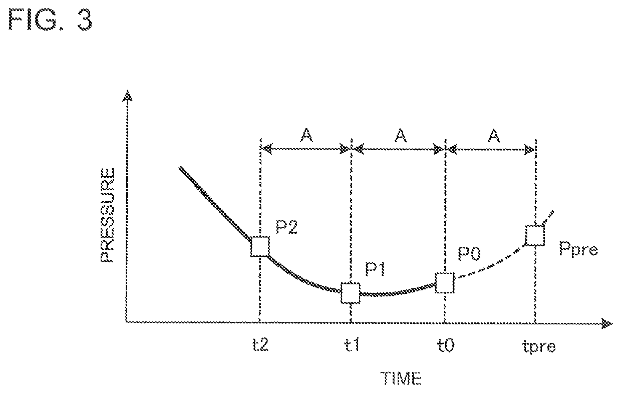
A refrigeration cycle apparatus includes a refrigerant circuit, a high-side pressure sensor, an outside air temperature sensor, an outdoor fan, a fan driving unit, and a controller. The controller includes a pressure prediction unit that predicts, based on a high-side pressure detected by the high-side pressure sensor, a predicted value of high-side pressure at the elapse of a set time, a fan rotation speed control unit that, during cooling operation in which an indoor heat exchanger acts as an evaporator, adjusts the rotation speed of the fan driving unit based on the outside air temperature detected by the outside air temperature sensor and the operating capacity of an indoor unit, and an intermittent fan control unit that, if the fan driving unit is running at a set lower limit rotation speed, and if the high-side pressure is below a target value, controls the fan driving unit to perform intermittent operation, the intermittent operation being performed by setting an ON time and an OFF time such that the predicted value predicted by the pressure prediction unit approaches the target value.

Description

CROSS REFERENCE TO RELATED APPLICATION[0001]This application is a U.S. national stage application of PCT / JP2016 / 076200 filed on Sep. 6, 2016, the contents of which are incorporated herein by reference.TECHNICAL FIELD[0002]The present invention relates to a refrigeration cycle apparatus that controls an outdoor fan under low outside air temperature conditions.BACKGROUND ART[0003]With conventional air-conditioning apparatuses, during cooling operation under low outside air temperature conditions, the temperature of the heat exchanger in the indoor unit reaches a temperature just short of the freezing temperature. An example of a control used to prevent this situation is to perform intermittent operation such that the compressor is stopped when the temperature of the heat exchanger in the indoor unit drops to a set temperature, and the operation of the compressor is resumed when the temperature of the heat exchanger reaches a predetermined temperature. Under such a control, the high-si...

Claims


Application Information

Patent Timeline
Patent Type & Authority Patents(United States)
IPC IPC(8): F25B49/02F24F11/871F25B13/00F24F11/86G05B13/04F25B1/00F25B39/04F24F110/12F24F110/40
CPCF25B49/025G05B13/048F24F11/871F25B13/00F24F11/86F25B49/027F25B1/00F25B39/04F24F2110/40F24F2110/12F25B2700/1933F25B2600/112F25B2700/21161F25B2313/0294F25B2700/21F25B2339/04F25B2313/031F25B2700/2106F25B2700/2117F25B2700/1931F25B2500/31Y02B30/70F25B2500/19
Inventor MORIMOTO, KOTA
Owner MITSUBISHI ELECTRIC CORP
Learn More