Drive device for hybrid vehicle

a hybrid vehicle and drive device technology, applied in the direction of electric propulsion mounting, transportation and packaging, gearing, etc., can solve the problems of large space, difficult to reduce the size of the drive device, and difficulty in reducing the size of the drive device, so as to reduce the size of the configuration, increase the torque of the second motor, and increase the torque of the engin

Active Publication Date: 2020-09-22
TOYOTA JIDOSHA KK
View PDF23 Cites 0 Cited by
  • Summary
  • Abstract
  • Description
  • Claims
  • Application Information

AI Technical Summary

Benefits of technology

[0008]An engine and a motor constituting a power source of a hybrid drive device have a difference in output characteristics of torque, and in a case where a speed reduction ratio of a speed reduction mechanism provided on an output side of the motor is made large to reduce the size of the motor, the difference in output torque becomes more conspicuous. In this case, a desirable speed reduction ratio in a power transmission system from the engine to the drive wheels becomes different from a desirable speed reduction ratio in a power transmission system from the motor to the drive wheels. The speed reduction ratios are easily set to desirable values, respectively, in a case where a speed reduction mechanism for the engine and a speed reduction mechanism for the motor are independently provided. However, the number of gear shift mechanisms increases, making it difficult to reduce the size of the drive device. In the device described in JP 9-226392 A, the second motor is coupled to the output element of the power split device, the three parallel gear type speed reduction mechanisms are arranged on the output side (the downstream side in the transmission direction of torque) of the second motor, and the speed reduction mechanisms are shared by the engine and the second motor. For this reason, it is possible to decrease the number of needed speed reduction mechanisms. However, in order to reduce the size of the second motor, in a case where the speed reduction ratio for the second motor is made larger, the speed reduction ratio for the engine becomes large. In particular, in the device described in JP 9-226392 A, since the carrier of the planetary gear mechanism constituting the power split device serves as an input element, the sun gear of the planetary gear mechanism serves as a reaction element, and the ring gear of the planetary gear mechanism serves as an output element, the gear ratio of the power split device at an operation point (mechanical point) in a state where the first motor is stopped to stop the rotation of the sun gear does not become sufficiently small (the speed increase ratio does not becomes sufficiently large), and as a result, an engine rotation speed may become high, causing a disadvantage in terms of improvement of fuel efficiency, and deterioration of NV characteristics, or the like may occur.
[0025]Then, according to the aspect of the disclosure, the second speed reduction unit or the differential gear is disposed to be offset with respect to the first speed reduction unit in the direction of the rotation center axis, whereby it is possible to equalize the lengths or the like of right and left drive shafts by disposing the differential gear near a central portion in a width direction of the vehicle. Alternatively, since the differential gear is positioned at one side of the vehicle in the vehicle width direction, the differential gear is easily coupled to the drive shafts.

Problems solved by technology

However, in a case where three parallel gear type speed reduction mechanisms are provided in series, a space is made large for this reason, and it is difficult to achieve reduction in size of the drive device.
However, the number of gear shift mechanisms increases, making it difficult to reduce the size of the drive device.

Method used


Image

  • Drive device for hybrid vehicle
  • Drive device for hybrid vehicle
  • Drive device for hybrid vehicle

Examples


Embodiment Construction

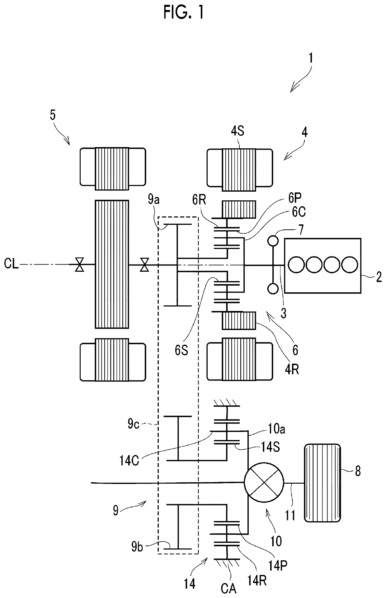
[0068]A drive device for a hybrid vehicle according to an embodiment of the disclosure can be constituted as a transaxle having a differential gear as a final drive gear, and an example thereof is schematically shown in FIG. 1. A drive device 1 is a horizontal storage type in which an output shaft 3 (or a rotation center axis CL) of an engine (ENG) 2 is disposed to be in parallel with a vehicle width direction, and is mounted in a front engine-front drive FF vehicle or a rear engine-rear drive RR vehicle. The drive device 1 includes the engine 2 and two motors 4, 5 as a drive power source. The engine 2 is an internal combustion engine, such as a gasoline engine or a diesel engine. Each of the motors 4, 5 is a so-called motor generator configured to generate electric power, and an example thereof is a permanent magnet type synchronous motor.

[0069]The first motor 4 primarily functions as a power generator at the time of non-stationary traveling, and the second motor 5 functions as a m...


PUM


Abstract

A drive device for a hybrid vehicle includes an engine, a first motor, a power split device, a second motor, a first speed reduction unit, a second speed reduction unit, and a differential gear. The first motor generates electric power. The power split device splits drive power output from the engine to the first motor side and a drive wheel side. The second motor increases or decreases torque output from the power split device and to be transmitted to the differential gear. The second motor is coupled to a sun gear. The first speed reduction unit is coupled to the sun gear. The second speed reduction unit is provided between the first speed reduction unit and the differential gear. The differential gear transmits torque to the drive wheel.

Description

INCORPORATION BY REFERENCE[0001]The disclosure of Japanese Patent Application No. 2017-203272 filed on Oct. 20, 2017 including the specification, drawings and abstract is incorporated herein by reference in its entirety.BACKGROUND1. Technical Field[0002]The present disclosure relates to a drive device for a hybrid vehicle including an engine and a motor as a drive power source.2. Description of Related Art[0003]Japanese Unexamined Patent Application Publication No. 9-226392 (JP 9-226392 A) discloses a drive device for a hybrid vehicle which is a drive device of a type of transmitting both of torque output from an engine and torque output from a motor to drive wheels. The configuration of the drive device will be described. A first motor, a drive sprocket, a power split device, and a second motor are disposed on the same axis as an engine and disposed in this order from the engine side. The power split device is a single-pinion planetary gear mechanism, the engine is coupled to a car...

Claims


Application Information

Patent Timeline
Patent Type & Authority Patents(United States)
IPC IPC(8): B60K6/445B60K6/40B60K6/365B60K6/26F16H37/08
CPCF16H37/0833B60K6/445F16H37/0806B60K6/40B60K6/26B60K6/365B60K2006/266B60Y2200/92B60K6/36Y02T10/62B60K6/24B60K6/48F16H3/72F16H7/06F16H57/037F16H2007/087F16H2200/202B60K1/02B60K6/20F16H3/44F16H48/06
Inventor HATA, KENSEIKOMADA, HIDEAKINISHIMINE, AKIKOMURAKAMI, AKIRA
Owner TOYOTA JIDOSHA KK
Why Eureka
Try Eureka