Secondary battery charging method, charging control apparatus, and secondary battery

a secondary battery and charging control technology, applied in secondary battery servicing/maintenance, electrochemical generators, transportation and packaging, etc., can solve the problems of reducing the service life of secondary batteries of lithium ions, cycle degradation, and reducing the time required until charging completion, so as to simplify the charging control. , the effect of reducing the time required to complete the charging

Active Publication Date: 2020-09-01
MURATA MFG CO LTD
View PDF19 Cites 2 Cited by
  • Summary
  • Abstract
  • Description
  • Claims
  • Application Information

AI Technical Summary

Benefits of technology

[0020]In the secondary battery charging method according to the first aspect of the present disclosure, the charging control apparatus according to the first aspect of the present disclosure, or the secondary battery according to the first aspect of the present disclosure,
[0021]since the operation or process of performing constant current charging until a first predetermined voltage V0 is attained, then performing constant voltage charging at the first predetermined voltage V0, completing the first constant voltage charging when a charge current becomes (In−ΔIn) from In, and then incrementing n by one, and
[0022]performing constant voltage charging at a voltage Vn=Vn-1+ΔVn, repeating a step of completing the n-th constant voltage charging when the charge current becomes (In−ΔIn) from In, by incrementing n by one, and completing the N-th constant voltage charging in which a value of the voltage Vn reaches a second predetermined voltage VN (>V0) to terminate the constant voltage charging, is performed,
[0023]cycle degradation does not occur even in a case where the charging time is tried to be shortened and the charging time is not lengthened even in a case where cycle degradation is tried to be suppressed. That is, in the constant voltage charging step, the charge voltage is increased stepwise so that the current value is decreased stepwise in a high electrical potential range during charging. For example, in a case where a lithium ion secondary battery is configured as the secondary battery, diffusion failure of lithium ions in a charge voltage range in which an electrical potential difference between an electrical potential of a positive electrode and an electrical potential of a negative electrode is large, is suppressed. As a result, capacity degradation in accordance with an increase in side reaction including precipitation of lithium is suppressed. Moreover, a time required until completion of charging is shortened by homogenization of lithium precipitation in the negative electrode. Further, it is sufficient for the constant voltage charging step to determine the first predetermined voltage V0, the second predetermined voltage VN, ΔVn, and ΔIn in advance, and thus simplification of charging control can be achieved. In addition, the lithium precipitation on the surface of the negative electrode is suppressed, and as a result, a change (increase) in the thickness of the secondary battery is suppressed. In the secondary battery charging method according to the second aspect of the present disclosure, the charging control apparatus according to the second aspect of the present disclosure, or the secondary battery according to the second aspect of the present disclosure, since the constant current charging is performed by combining a constant current value k1·I0 (provided that, 0.4<k1<1) and the constant current value I0, cycle degradation can be suppressed. Incidentally, the effects described in this specification are merely examples and are not limited, and additional effects may be demonstrated.

Problems solved by technology

In addition, charging the lithium ion secondary batteries in a short time while degradation in capacity at the time of long-term use (cycle degradation) is suppressed becomes an important problem.

Method used


Image

  • Secondary battery charging method, charging control apparatus, and secondary battery
  • Secondary battery charging method, charging control apparatus, and secondary battery
  • Secondary battery charging method, charging control apparatus, and secondary battery

Examples


example 2c

, and

[0039]FIGS. 16A and 16B are a graph showing cycle characteristics and a graph showing the cycle transition of a charging time in the secondary battery charging method of Example 2A, Example 2B, Example 2C, Example 1A, and Comparative Example 1A, respectively.

[0040]FIG. 17A is a graph showing a relation between a charge voltage and a charge current with respect to a depth of charge at the first cycle in a secondary battery charging method of Example 2D and Example 2E and FIG. 17B is a graph showing a relation between a charge voltage and a charge current with respect to a depth of charge at the first cycle in a secondary battery charging method of Example 2F.

[0041]FIGS. 18A and 18B are a graph showing cycle characteristics and a graph showing the cycle transition of a charging time in the secondary battery charging method of Example 2D, Example 2E, Example 1A, and Comparative Example 1A, respectively.

[0042]FIGS. 19A and 19B are a graph showing cycle characteristics and a graph s...

example 1

[0080]Example 1 relates to the secondary battery charging method according to the first aspect of the present disclosure and the secondary battery according to the first aspect of the present disclosure.

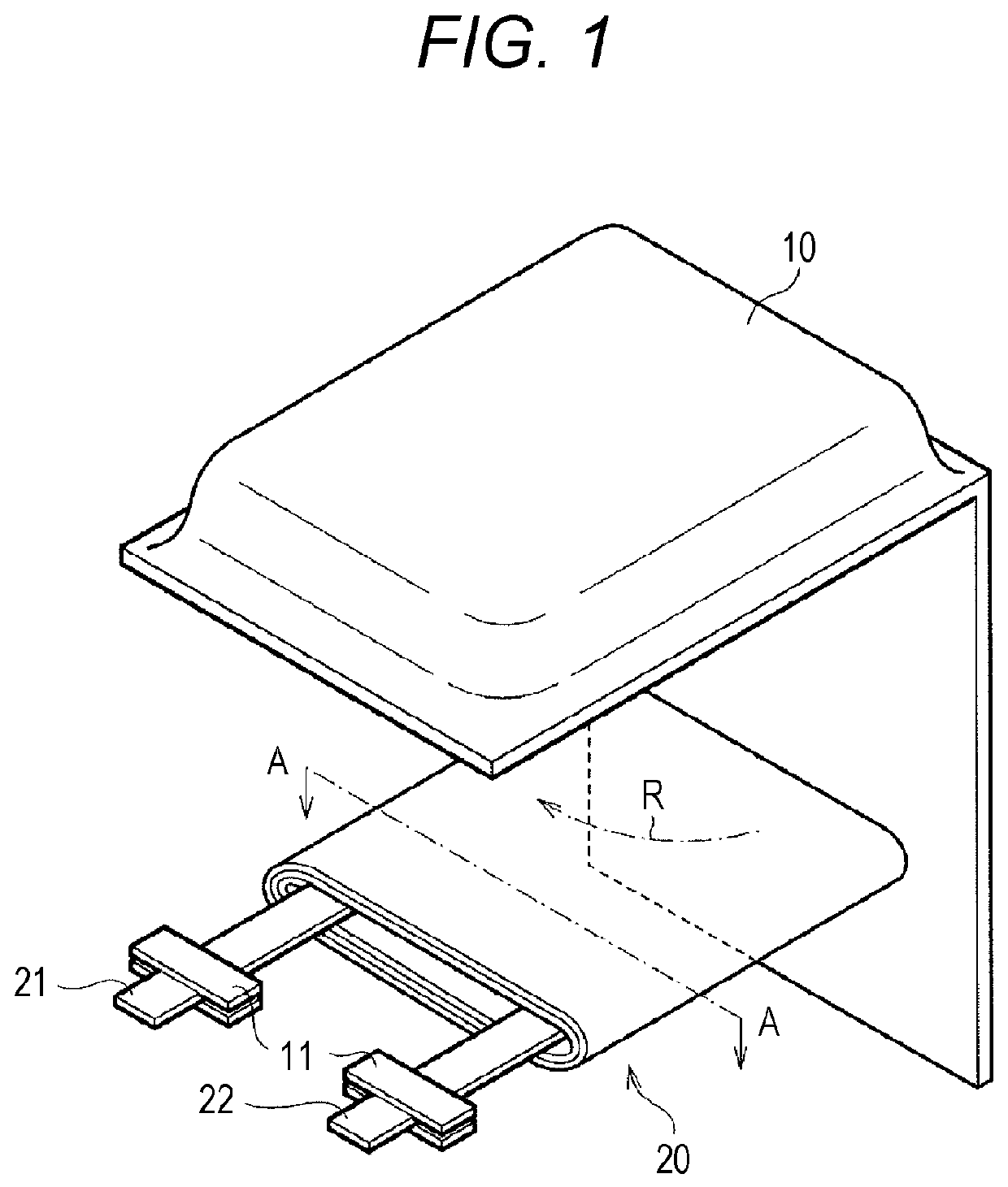
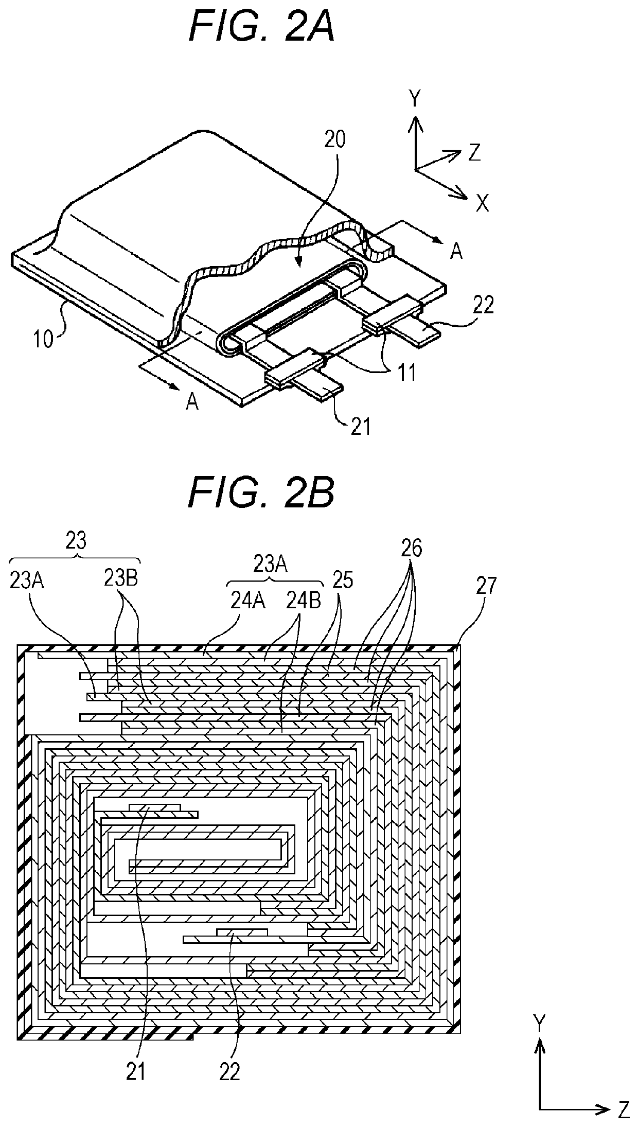
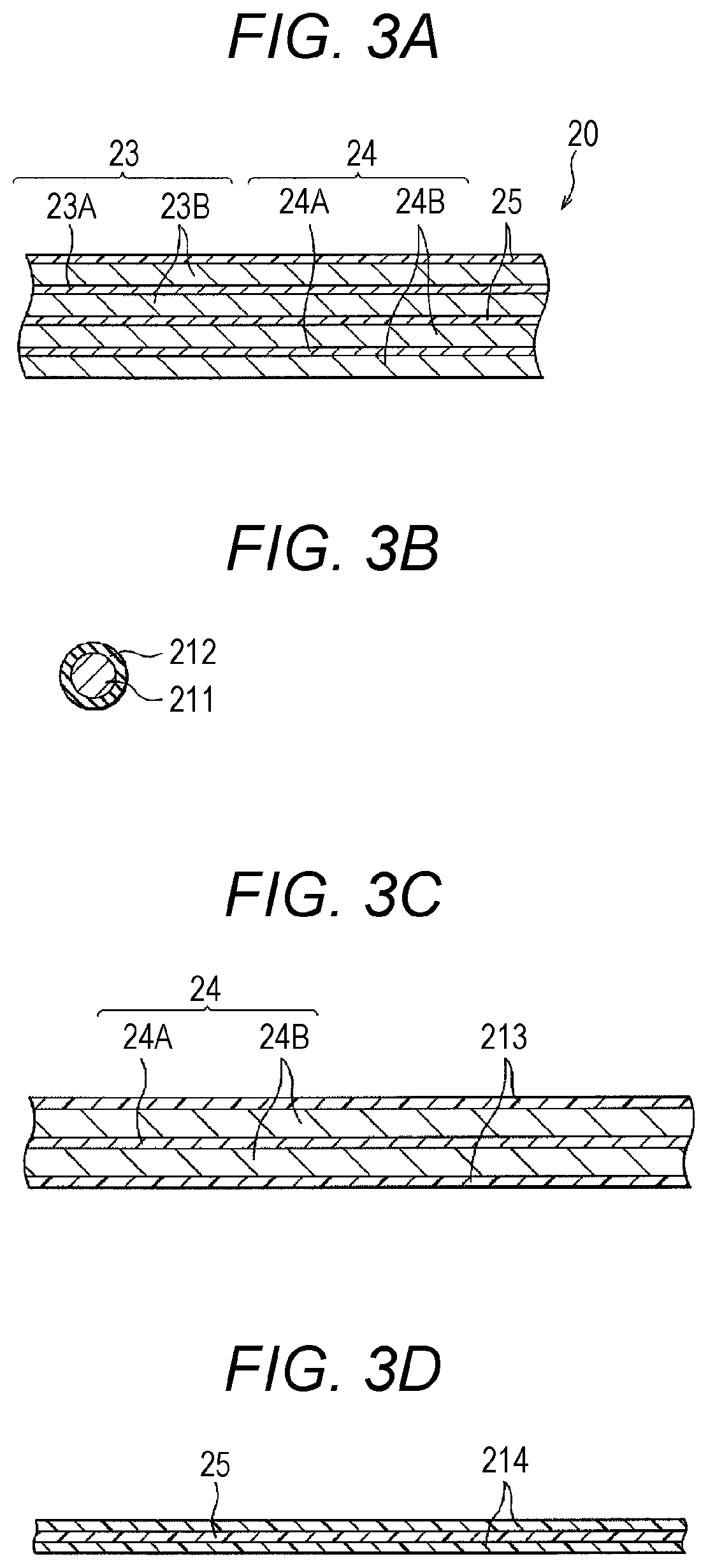
[0081]A secondary battery of Example 1 or a secondary battery of Example 2 to be described later is configured as a lithium ion secondary battery, and specifically, for example, is configured as a flat laminated film type lithium ion secondary battery, and a positive electrode, a separator, and a negative electrode are spirally wound. A schematic exploded perspective view of the lithium ion secondary battery is illustrated in FIG. 1 and FIG. 2A, and a schematic enlarged cross-sectional view taken along arrow A-A of a spirally wound electrode body (structure) illustrated in FIG. 1 and FIG. 2A (a schematic enlarged cross-sectional view taken along a YZ plane) is illustrated in FIG. 2B. Furthermore, a schematic partial cross-sectional view in which a part of the spirally wound electrode...

example 1b

[0126]Next, in Example 1B, specifically, the first predetermined voltage V0 was set to 4.30 V, and the second predetermined voltage VN was set to 4.35 V. The first predetermined voltage V0 is a voltage when a depth of charge (SOC value) became 67%.

[0127]More specifically, in Example 1B, N was set to five. In addition, the value of ΔVn is positive and negative. More specifically, values of Vn-1, ΔVn, Vn, In, ΔIn, and (In−ΔIn) in each constant voltage charging were set as described in the following Table 4. The charge current at the time of constant current charging was set to 2930 mA.

[0128]

TABLE 4nVn−1ΔVnVnInΔInIn −ΔIn14.302930488244224.300.014.312442489195334.310.094.40195397697744.40−0.064.3497748948854.340.014.35488341147

[0129]A relation between a charge voltage and a charge current with respect to a depth of charge (SOC value) at the first cycle is shown in FIG. 9A. Further, a relation between a charge voltage and a charge current with respect to a charging time at the first cycl...


PUM

PropertyMeasurementUnit
charge currentaaaaaaaaaa

Abstract

In a secondary battery charging method, constant current charging is performed until a first predetermined voltage V0 is attained, constant voltage charging is then performed at the first predetermined voltage V0, the first constant voltage charging is completed when a charge current becomes (In−ΔIn) from In, and then n is incremented by one; and constant voltage charging is performed at a voltage Vn=Vn-1+ΔVn, a step of completing the n-th constant voltage charging when the charge current becomes (In−ΔIn) from In is repeated by incrementing n by one, and the N-th constant voltage charging in which a value of the voltage Vn reaches a second predetermined voltage VN (>V0) is completed to terminate the constant voltage charging.

Description

CROSS REFERENCE TO RELATED APPLICATIONS[0001]This application is a national stage application under 35 U.S.C. 371 and claims the benefit of PCT Application No. PCT / JP2016 / 064283 having an international filing date of 13 May 2016, which designated the United States, which PCT application claimed the benefit of Japanese Patent Application No. 2015-155738 filed 6 Aug. 2015 and Japanese Patent Application No. 2016-083477 filed 19 Apr. 2016, the disclosures of which are incorporated herein by reference in their entirety.TECHNICAL FIELD[0002]The present disclosure relates to a secondary battery charging method, a charging control apparatus, and a secondary battery.BACKGROUND ART[0003]With widespread of portable electronic apparatuses and the like, lithium ion secondary batteries are regarded as important devices as power sources therefor. Further, with widespread of smartphones and wearable instruments in recent years, high safety, high life span, high energy density, and the like are req...

Claims


Application Information

Patent Timeline
Patent Type & Authority Patents(United States)
IPC IPC(8): H02J7/00H01M10/44H02J7/02H02J7/14B60L53/20H01M10/0525
CPCH02J7/007184H02J7/02H01M10/44H02J7/00718B60L53/20H01M10/0525Y02E60/10Y02T10/70Y02T10/7072Y02T90/14
Inventor HORIUCHI, YUTOSHIMIZU, YOSHIFUMITANAKA, MASATOMO
Owner MURATA MFG CO LTD
Why Eureka
Try Eureka