Secondary battery charging method, charging control apparatus, and secondary battery

Active Publication Date: 2018-05-31
MURATA MFG CO LTD
View PDF11 Cites 4 Cited by
  • Summary
  • Abstract
  • Description
  • Claims
  • Application Information

AI Technical Summary

Benefits of technology

This patent describes a method for charging secondary batteries to address issues of cycle degradation and capacity degradation during charging. The method involves performing constant current charging until a certain voltage is reached, then performing constant voltage charging at a higher voltage until the battery is fully charged. This approach prevents cycle degradation and promotes capacity utilization. The method also simplifies charging control and reduces thickness of the battery. Overall, this method improves the longevity and performance of secondary batteries.

Problems solved by technology

In addition, charging the lithium ion secondary batteries in a short time while degradation in capacity at the time of long-term use (cycle degradation) is suppressed becomes an important problem.

Method used


Image

  • Secondary battery charging method, charging control apparatus, and secondary battery
  • Secondary battery charging method, charging control apparatus, and secondary battery
  • Secondary battery charging method, charging control apparatus, and secondary battery

Examples


example 2c

, and

[0038]FIGS. 16A and 16B are a graph showing cycle characteristics and a graph showing the cycle transition of a charging time in the secondary battery charging method of Example 2A, Example 2B, Example 2C, Example 1A, and Comparative Example 1A, respectively.

[0039]FIG. 17A is a graph showing a relation between a charge voltage and a charge current with respect to a depth of charge at the first cycle in a secondary battery charging method of Example 2D and Example 2E and FIG. 17B is a graph showing a relation between a charge voltage and a charge current with respect to a depth of charge at the first cycle in a secondary battery charging method of Example 2F.

[0040]FIGS. 18A and 18B are a graph showing cycle characteristics and a graph showing the cycle transition of a charging time in the secondary battery charging method of Example 2D, Example 2E, Example 1A, and Comparative Example 1A, respectively.

[0041]FIGS. 19A and 19B are a graph showing cycle characteristics and a graph s...

example 1

[0079]Example 1 relates to the secondary battery charging method according to the first aspect of the present disclosure and the secondary battery according to the first aspect of the present disclosure.

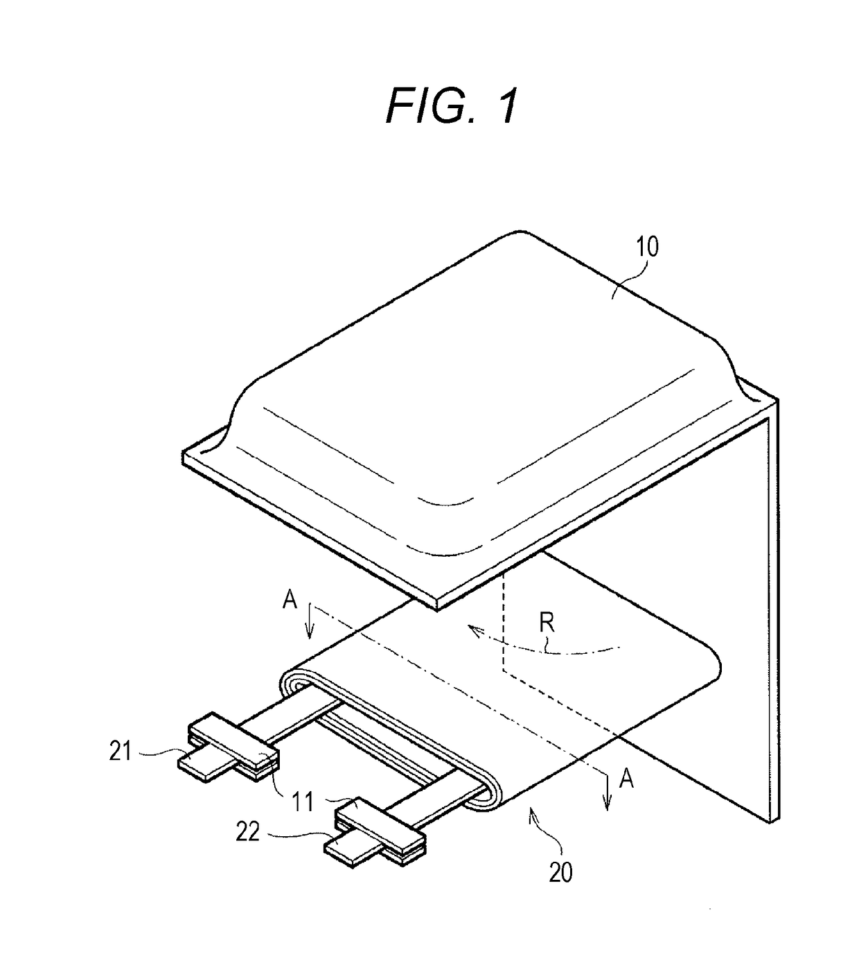
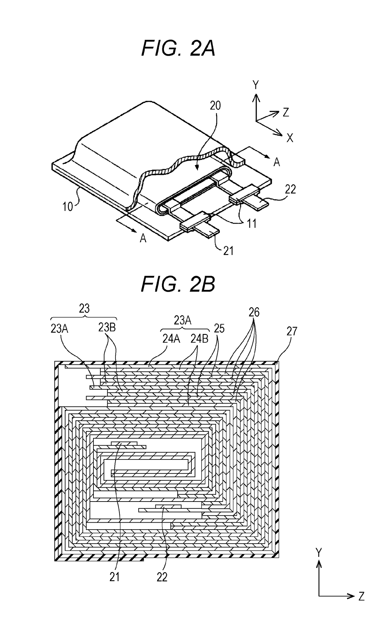
[0080]A secondary battery of Example 1 or a secondary battery of Example 2 to be described later is configured as a lithium ion secondary battery, and specifically, for example, is configured as a flat laminated film type lithium ion secondary battery, and a positive electrode, a separator, and a negative electrode are spirally wound. A schematic exploded perspective view of the lithium ion secondary battery is illustrated in FIG. 1 and FIG. 2A, and a schematic enlarged cross-sectional view taken along arrow A-A of a spirally wound electrode body (structure) illustrated in FIG. 1 and FIG. 2A (a schematic enlarged cross-sectional view taken along a YZ plane) is illustrated in FIG. 2B. Furthermore, a schematic partial cross-sectional view in which a part of the spirally wound electrode...

example 1b

[0122]Next, in Example 1B, specifically, the first predetermined voltage V0 was set to 4.30 V, and the second predetermined voltage VN was set to 4.35 V. The first predetermined voltage V0 is a voltage when a depth of charge (SOC value) became 67%.

[0123]More specifically, in Example 1B, N was set to five. In addition, the value of ΔVn is positive and negative. More specifically, values of Vn-1, ΔVn, Vn, In, ΔIn, and (In−ΔIn) in each constant voltage charging were set as described in the following Table 4. The charge current at the time of constant current charging was set to 2930 mA.

TABLE 4nVn−1ΔVnVnInΔInIn −ΔIn14.302930488244224.300.014.312442489195334.310.094.40195397697744.40−0.064.3497748948854.340.014.35488341147

[0124]A relation between a charge voltage and a charge current with respect to a depth of charge (SOC value) at the first cycle is shown in FIG. 9A. Further, a relation between a charge voltage and a charge current with respect to a charging time at the first cycle is s...


PUM


Abstract

In a secondary battery charging method, constant current charging is performed until a first predetermined voltage V0 is attained, constant voltage charging is then performed at the first predetermined voltage V0, the first constant voltage charging is completed when a charge current becomes (In−ΔIn) from In, and then n is incremented by one; and constant voltage charging is performed at a voltage Vn=Vn-1+ΔVn, a step of completing the n-th constant voltage charging when the charge current becomes (In−ΔIn) from In is repeated by incrementing n by one, and the N-th constant voltage charging in which a value of the voltage Vn reaches a second predetermined voltage VN (>V0) is completed to terminate the constant voltage charging.

Description

TECHNICAL FIELD[0001]The present disclosure relates to a secondary battery charging method, a charging control apparatus, and a secondary battery.BACKGROUND ART[0002]With widespread of portable electronic apparatuses and the like, lithium ion secondary batteries are regarded as important devices as power sources therefor. Further, with widespread of smartphones and wearable instruments in recent years, high safety, high life span, high energy density, and the like are required in the lithium ion secondary batteries. In addition, charging the lithium ion secondary batteries in a short time while degradation in capacity at the time of long-term use (cycle degradation) is suppressed becomes an important problem.[0003]In this regard, as a charging method for a lithium ion secondary battery of the related art, there are used methods such as a constant current and constant voltage method (CC-CV method) in which charging is started at a constant current and charging is performed at the tim...

Claims


Application Information

Patent Timeline
IPC IPC(8): H02J7/00H01M10/44H01M10/0525
CPCH02J7/0081H01M10/44H01M10/0525H02J7/0083B60L11/1811H02J7/02B60L53/20Y02E60/10Y02T10/70Y02T10/7072Y02T90/14H02J7/007184H02J7/00718
Inventor HORIUCHI, YUTOSHIMIZU, YOSHIFUMITANAKA, MASATOMO
Owner MURATA MFG CO LTD
Why Eureka
Try Eureka