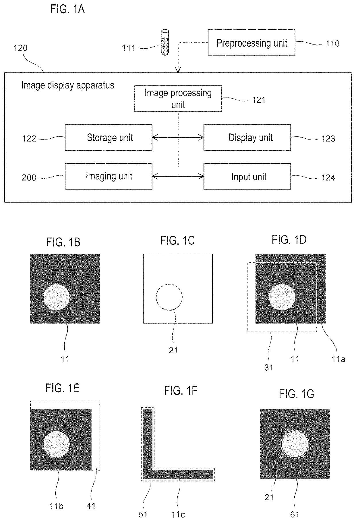
Image display apparatus, image display method, and image processing method
a technology of image display and test substance, which is applied in the field of image display apparatus, image display method, image processing method for imaging and displaying test substance, can solve the problems of lowering the operation efficiency, and achieve the effect of smooth and efficient operation, easy confirmation of the distribution state of bcr gene, and smooth diagnosis
- Summary
- Abstract
- Description
- Claims
- Application Information
AI Technical Summary
Benefits of technology
Problems solved by technology
Method used
Image

Examples
first embodiment
Padding Process
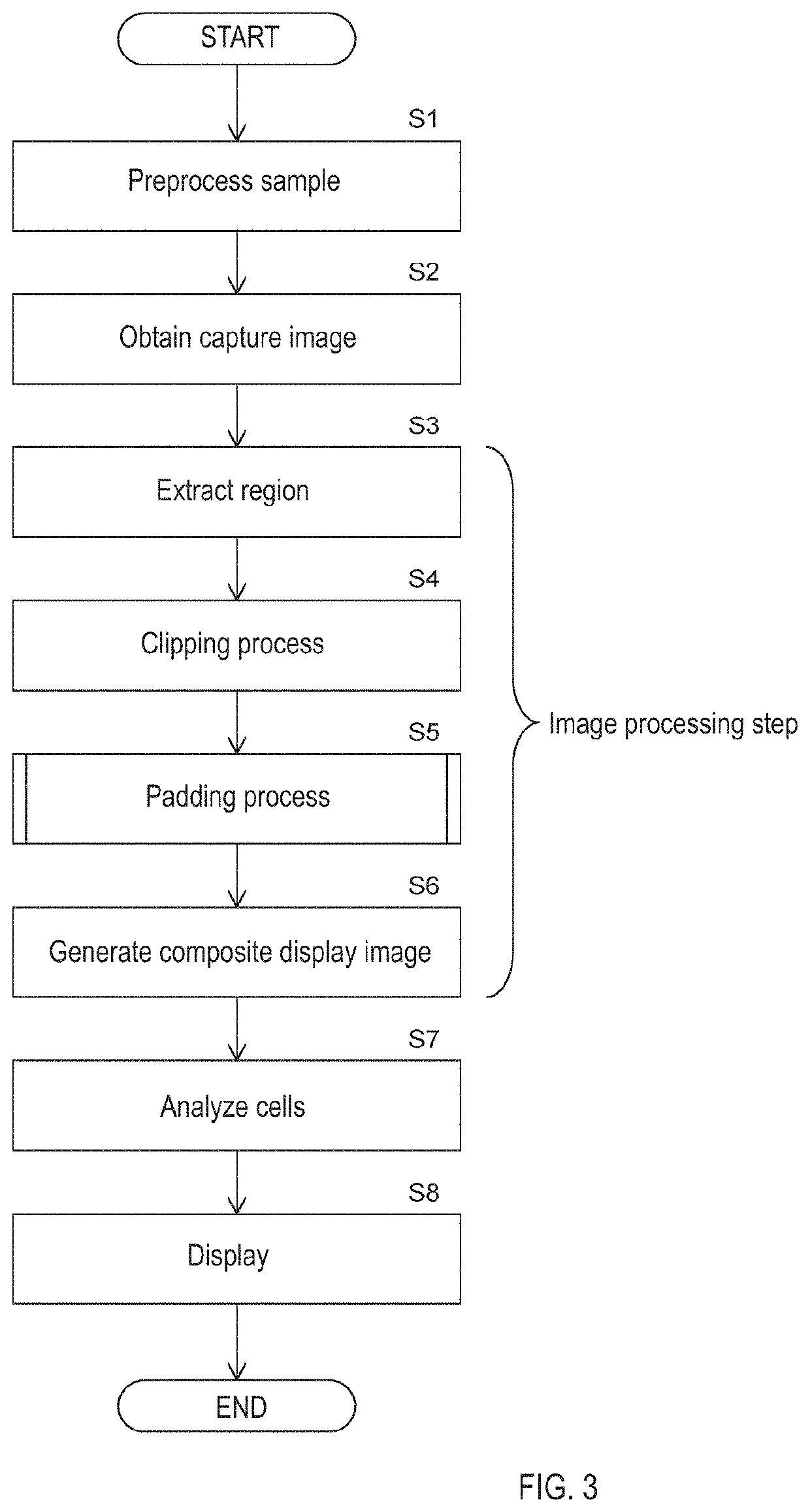
[0127]A padding process according to the first embodiment will be described with reference to FIG. 9. Note that since the padding process for the captured images 11 to 14 that have been subjected to the clipping process is the same in each instance, only the case of the captured image 11 based on the nucleus will be described in the following description for convenience. Hereinafter, each step of FIG. 9 will be described with reference to FIGS. 10A to 11A as appropriate.
[0128]As shown in FIG. 10A, in the clipping process performed before the padding process, the deleted image 11a is removed from the captured image 11, so that the image 11b is generated as described above. When the padding process is started, in step S11, the image processing unit 121 reads the pixel value of each pixel in the background region 91 other than the nucleus area 21 in the image 11b. The background region 91 is a hatched area in FIG. 10B.
[0129]Here, in order to recognize the background regi...
second embodiment
[0143]The second embodiment differs from the first embodiment only in the padding process. As shown in FIG. 14A, the padding process of the second embodiment is different from the padding process of the first embodiment shown in FIG. 9 in that step S21 is added instead of step S12, and step S22 is added instead of step S13. Steps different from the padding process of the first embodiment will be described below.
[0144]In step S21, the image processing unit 121 acquires the maximum pixel value and the minimum pixel value of the pixels in the background region 91 of the image 11b as background information. Then, in step S22, the image processing unit 121 sets the pixel value of each pixel of the additional image 11c with a random number that changes between the maximum pixel value and the minimum pixel value as shown in FIG. 14B.
[0145]When the pixel value of each pixel of the additional image 11c is set in this way, the noise component expressed in the additional image 11c becomes less...
third embodiment
[0150]The third embodiment differs from the first embodiment only in the padding process. As shown in FIG. 16A, the padding process according to the third embodiment is different from the padding process of the first embodiment shown in FIG. 9 in that step S31 is added following step S14. Steps different from the padding process of the first embodiment will be described below.
[0151]In step S14, an additional image 11c is added to the image 11b to generate a display image 61. In step S31, the image processing unit 121 performs a smoothing process on the display image 61 to suppress pixel value change. As shown in FIG. 16B, the smoothing process application region is a region obtained by removing the nucleus region 21 of the test substance from the entire region of the display image 61. Note that the smoothing process application region may be set to include at least the vicinity of the boundary between the additional image 11c and the background region 91 of the captured image 11.
[01...
PUM
 Abstract
Description
Claims
Application Information
 - R&D
- Intellectual Property
- Life Sciences
- Materials
- Tech Scout
- Unparalleled Data Quality
- Higher Quality Content
- 60% Fewer Hallucinations
Browse by: Latest US Patents, China's latest patents, Technical Efficacy Thesaurus, Application Domain, Technology Topic, Popular Technical Reports.
© 2025 PatSnap. All rights reserved.Legal|Privacy policy|Modern Slavery Act Transparency Statement|Sitemap|About US| Contact US: help@patsnap.com