
Pseudo differential receiving mechanism for single-ended signaling

a single-ended signaling and differential receiving technology, applied in the field of pseudo differential receiving mechanism for single-ended signaling, can solve the problems of reducing the signal swing used for boolean logic, creating electrical interference on neighboring metal traces and adjacent devices, and noise margin

Active Publication Date: 2020-08-18
ADVANCED MICRO DEVICES INC
View PDF28 Cites 3 Cited by
  • Summary
  • Abstract
  • Description
  • Claims
  • Application Information

AI Technical Summary

Problems solved by technology

For example, the electromagnetic fields for the metal traces conducting signals and the return current on the ground plane create electrical interference on neighboring metal traces and on adjacent devices.
As the operating voltage continues to decrease to reduce power consumption, the signal swing used for Boolean logic decreases as well as the noise margin.

Method used


Image

  • Pseudo differential receiving mechanism for single-ended signaling
  • Pseudo differential receiving mechanism for single-ended signaling
  • Pseudo differential receiving mechanism for single-ended signaling

Examples


Embodiment Construction

[0010]In the following description, numerous specific details are set forth to provide a thorough understanding of the methods and mechanisms presented herein. However, one having ordinary skill in the art should recognize that the various embodiments may be practiced without these specific details. In some instances, well-known structures, components, signals, computer program instructions, and techniques have not been shown in detail to avoid obscuring the approaches described herein. It will be appreciated that for simplicity and clarity of illustration, elements shown in the figures have not necessarily been drawn to scale. For example, the dimensions of some of the elements may be exaggerated relative to other elements.

[0011]Various systems, apparatuses, methods, and computer-readable mediums for receiving information as signals in a computing system are disclosed. In various embodiments, a computing system includes one or more functional blocks for processing applications. Exa...


PUM


Abstract

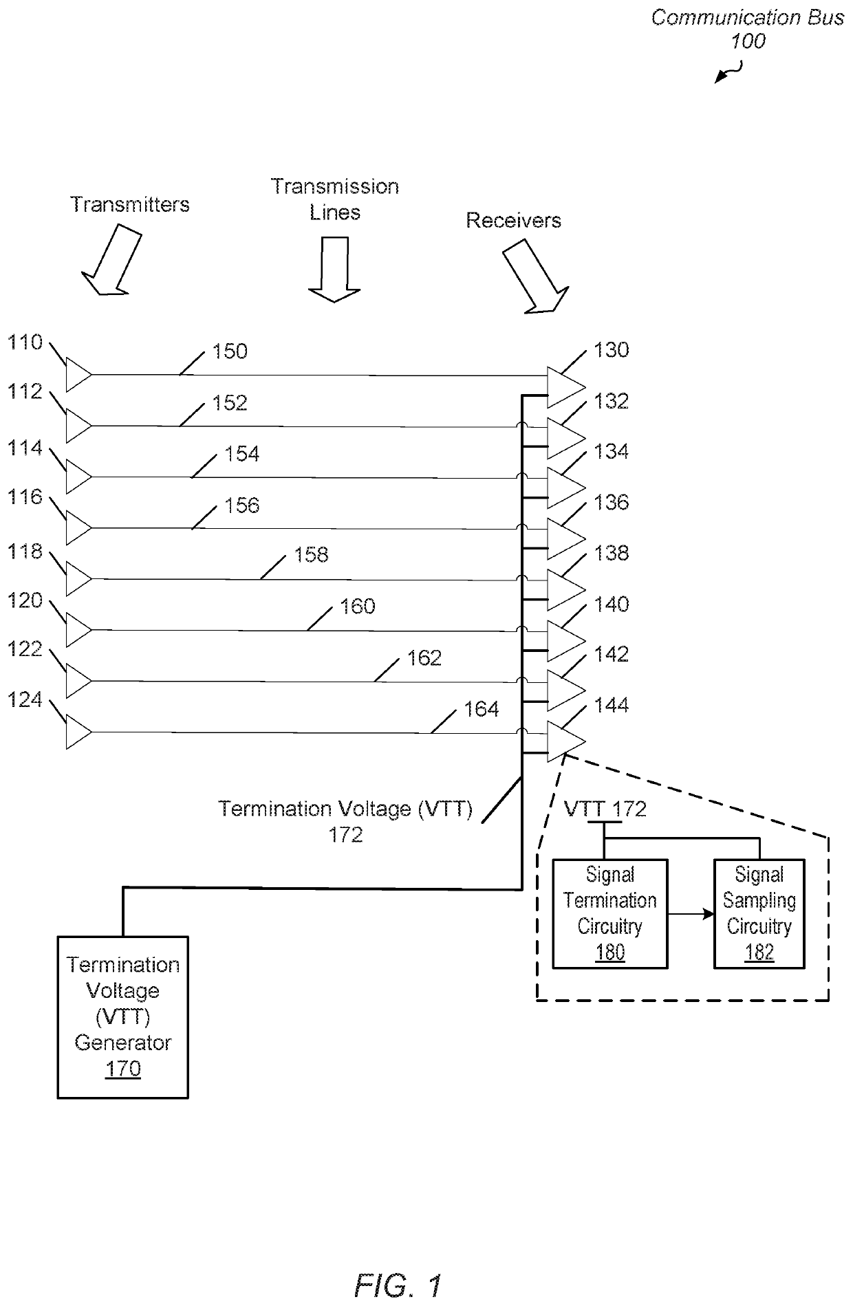
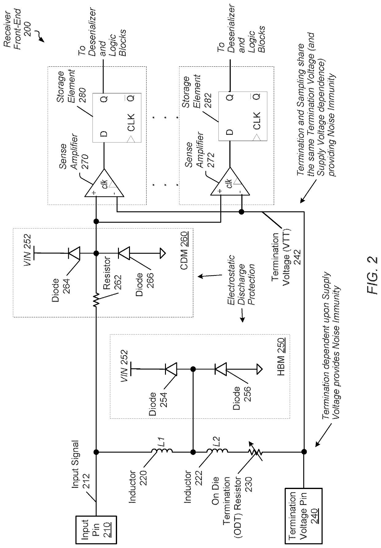
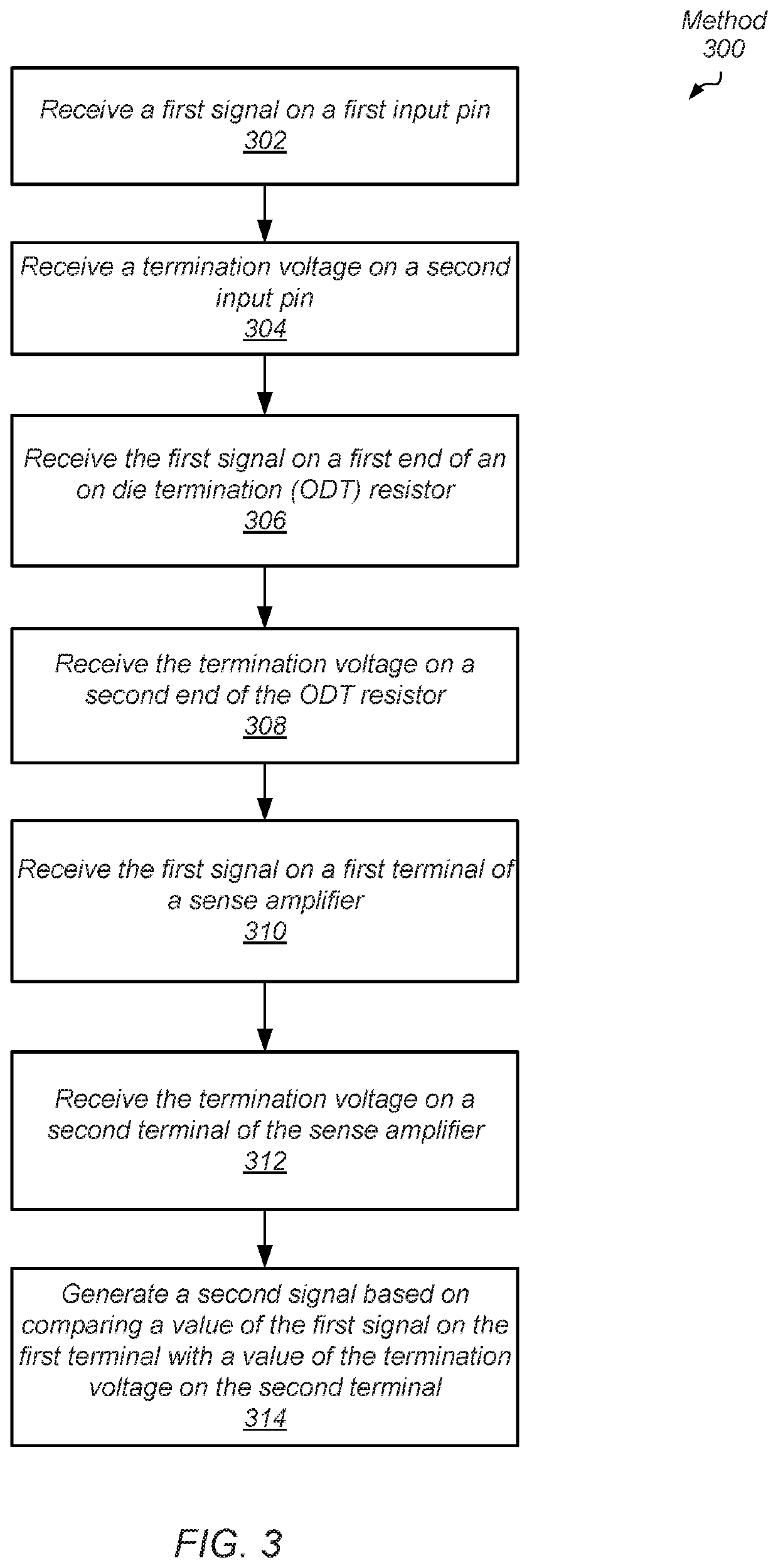
Systems, apparatuses, and methods for performing efficient data transfer in a computing system are disclosed. A computing system includes multiple transmitters sending singled-ended data signals to multiple receivers. A termination voltage is generated and sent to the multiple receivers. The termination voltage is coupled to each of signal termination circuitry and signal sampling circuitry within each of the multiple receivers. Any change in the termination voltage affects the termination circuitry and affects comparisons performed by the sampling circuitry. Received signals are reconstructed at the receivers using the received signals, the signal termination circuitry and the signal sampling circuitry.

Description

BACKGROUNDDescription of the Related Art[0001]When transferring information between functional blocks in a semiconductor chip, electrical signals are sent on multiple, parallel metal traces. Transmitters in a first functional block send the electrical signals across the parallel metal traces. Receivers in a second functional block receive the electrical signals. In some cases, the two functional blocks are within a same die. In other cases, the two functional blocks are on separate dies. In either case, the metal traces have transmission line effects such as distributed inductance, capacitance and resistance throughout its length. For modern integrated circuits, the interconnect capacitance reduces signal integrity and signal transfer rate more so than gate capacitance of semiconductor devices.[0002]The interconnect capacitance per unit length includes both sidewall fringing capacitance and cross-coupling capacitance. For example, the electromagnetic fields for the metal traces cond...

Claims


Application Information

Patent Timeline
Patent Type & Authority Patents(United States)
IPC IPC(8): H04B1/04H03M1/80H04B1/16H01L27/02
CPCH01L27/0248H04B1/16H04B1/04H03M1/808H03F2200/129H03F1/52H03F3/24H03F2200/444H03F1/26
Inventor SINGH, BALWINDERPARASCHOU, MILAMGALLUN, CHAD S.COOPER, JEFFREYGONZALES, DEAN E.AMBUNDO, ALUSHULLA JACKLIKENS, III, THOMAS H.TALBOT, GERALD R.
Owner ADVANCED MICRO DEVICES INC
Learn More