Heat exchanger

a technology of heat exchanger and heat exchanger plate, which is applied in the direction of indirect heat exchanger, stationary tubular conduit assembly, light and heating apparatus, etc., can solve the problems of fluid turbulence towards, and achieve the effect of reducing energy consumption, increasing flow rate, and high flow ra

Active Publication Date: 2020-08-11
HEATHWORK AS
View PDF45 Cites 1 Cited by
  • Summary
  • Abstract
  • Description
  • Claims
  • Application Information

AI Technical Summary

Benefits of technology

[0012]Consequently, there is a need to provide a heat exchanger that ensures a high flow with a minimum of energy consumption to provide the flow. It is also a need to provide a heat exchanger where there is a minimum of loss of pressure difference with an increased flow rate.
[0013]Another advantage of the heat exchanger according to the invention is that the surface area of the heat-exchanging element is higher, which results in a more efficient heat transfer. The ribs and fins of the heat exchanger element is adapted to fill the entire cross-sectional area of the heat exchanger so that there are no voids between the heat exchanger elements or the casing and the heat exchanger elements. The heat exchanger elements have a compact structure where the heat transferring area is as great as possible. The heat could thereby be transferred evenly from the first fluid to the second fluid throughout the whole heat exchanger.
[0014]A pipe with an inclined opening at the free end will provide better heat transfer to the inner surface of the core. The inclined surface results in a cavitation at the pipe outlet which will lead to turbulence in the fluid towards the inner surface of the core. The turbulence will result in better and more efficient heat transfer from the fluid to the core.
[0015]The fins and the ribs have substantially the same thickness in along the radial distance from the core. This provides a better and also more even heat transfer from the ribs / fins to the second fluid throughout the whole heat exchanger.
[0016]The material of the heat exchanger causes less incrustation. The exchanger elements are also easier to clean because it can be done by a high-pressure washer. A smooth surface of the ribs / fins is also advantageous in that the fluid can flow through the heat exchanger with a minimum of obstacles. The element could also be made by extrusion. This provides easier production of the elements.

Problems solved by technology

The inclined surface results in a cavitation at the pipe outlet which will lead to turbulence in the fluid towards the inner surface of the core.

Method used


Image

  • Heat exchanger
  • Heat exchanger
  • Heat exchanger

Examples


Embodiment Construction

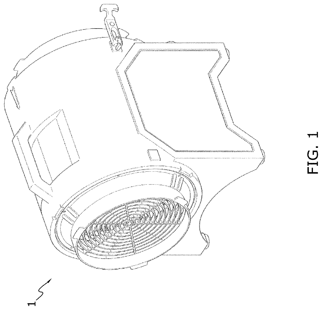
[0045]FIG. 1 illustrates a heat exchanger 1. It facilitates transfer of thermal energy between two or more fluids. The fluids may include liquid, gasses or any combination of liquid and gases. For example, the fluids may include air, exhaust, oil, coolant, water or any other fluid known in the art. The heat exchanger may be used to transfer thermal energy in any fluid systems, such as for example, an exhaust and / or air cooling system, a radiator system, an oil cooling system, a condenser system or any other type of fluid system known in the art.

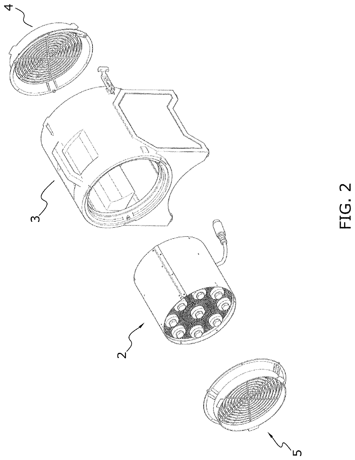
[0046]FIG. 2 shows a partially exploded, elevated view of the heat exchanger according to one embodiment of the invention. The heat exchanger 1 comprising a housing 3. This housing 3 is shown cylindrically shaped but it could also have other shapes, like a rectangular shape.

[0047]A heat exchanger 2 according to the embodiment of the invention is arranged within the housing 3. At both ends of the housing 3, there are arranged lattices 4, 5 to ...


PUM


Abstract

A heat exchanger for transferring heat between two fluids with different temperature includes a first heat exchange element having at least one core extending longitudinally through the heat exchange element. The at least one core defines a core cavity that is configured with an inlet port and an outlet port to receive a first fluid flowing therethrough. The heat exchange element includes ribs extending continuously substantially in parallel with the at least one core along the whole length of the core. The ribs extend radially outwardly from the core and are exposed to contact with a second fluid that flows along said ribs. Each rib is divided into at least two radially extending fins at a radial distance from the core. Each fin extends to a proximity of an outer casing surrounding the first heat exchanger element or a proximity of fins of an adjacent heat exchanger element.

Description

FIELD OF THE INVENTION[0001]The present invention relates to a heat exchanger, whereby a first fluid having a first temperature heats up or cools down a second fluid having a second temperature.TECHNICAL BACKGROUND OF THE INVENTION[0002]In general, heat exchangers are devices that transfer thermal energy between two fluids without direct contact between the two fluids. A primary fluid is typically directed through a fluid core of the heat exchanger while a secondary cooling or heating fluid is brought into external contact with the fluid core. In this manner, thermal energy may be transferred between the primary and secondary fluids through the walls of the fluid core.[0003]The ability of the heat exchanger to transfer thermal energy between the primary and secondary fluids depends on, amongst other things, the surface available for the heat transfer and the thermal properties of the exchanger materials.[0004]A vast number of various types of heat exchangers exist in the field. One ...

Claims


Application Information

Patent Timeline
Patent Type & Authority Patents(United States)
IPC IPC(8): F28D7/12F28D7/08F28F1/20F28F1/42F28F1/26F28F1/16F28D1/047F28F1/40
CPCF28D1/0475F28F1/16F28F1/20F28F1/26F28F1/40F28D7/12F28D7/085F28F1/422F28F2220/00F28F2255/16F28F2215/10F28F2275/205F28F2230/00
Inventor MARKUSSEN, ALMAR
Owner HEATHWORK AS
Why Eureka
Try Eureka