Impact energy absorber

a technology of energy absorber and impact, which is applied in the direction of buffer, sheet joining, fastening means, etc., can solve the problems of unsuitable direct application, and achieve the effects of increasing the modulus of rigidity, simple construction, and increasing lateral forces

Active Publication Date: 2020-08-11
AXTONE SPOLKA AKCYJNA
View PDF33 Cites 0 Cited by
  • Summary
  • Abstract
  • Description
  • Claims
  • Application Information

AI Technical Summary

Benefits of technology

[0006]The purpose of the invention is to develop a device absorbing the impact energy by means of machining, which device has an increased modulus of rigidity, transmits tractive forces, impact forces and increased lateral forces, and at the same time has a simple construction.
[0028]The execution of the energy absorbing element as two parallel rods placed at a distance from one another and connected with the mounting plates also placed at a distance from one another allows to achieve the structure with an increased modulus of rigidity which is capable of transmitting greater lateral forces acting in the extreme operating conditions of the device. Such a solution allows a movement of the tool mounting plate in a perpendicular direction relative to the rods, influencing the even operation of the cutting tools.
[0029]Using a thrust element between the machining unit and the rods to transmit the tractive force allows to use the device of the invention also in the function of a coupler assembly. To this end, the device comprises also a tool mounting plate which facilitates fastening of the device of the invention to cooperating, neighbouring elements of a rail carriage on one side of the rod. On the other side of the rod, the device according to the invention is mounted to the cooperating, neighbouring elements of a rail carriage via a second mounting plate fastened at a distance from the tool mounting plate. Fastening of both plates on the rods at a distance from one another allows their movement towards each other when the pre-set threshold value of the impact force has been exceeded.
[0030]Execution of the thrust element in the form of a thrust ring fastened in the end part of the rod facilitates the assembly of the device according to the invention. Such a structure simplifies also the construction of one combined element wherein the thrust element is coupled with the safety intermediate element.

Problems solved by technology

Known devices perform well their task of absorbing the kinetic energy of impacts but they are unsuitable for a direct application as devices which transmit axial forces, alternating compressive and tensile ones.

Method used


Image

  • Impact energy absorber
  • Impact energy absorber
  • Impact energy absorber

Examples


Embodiment Construction

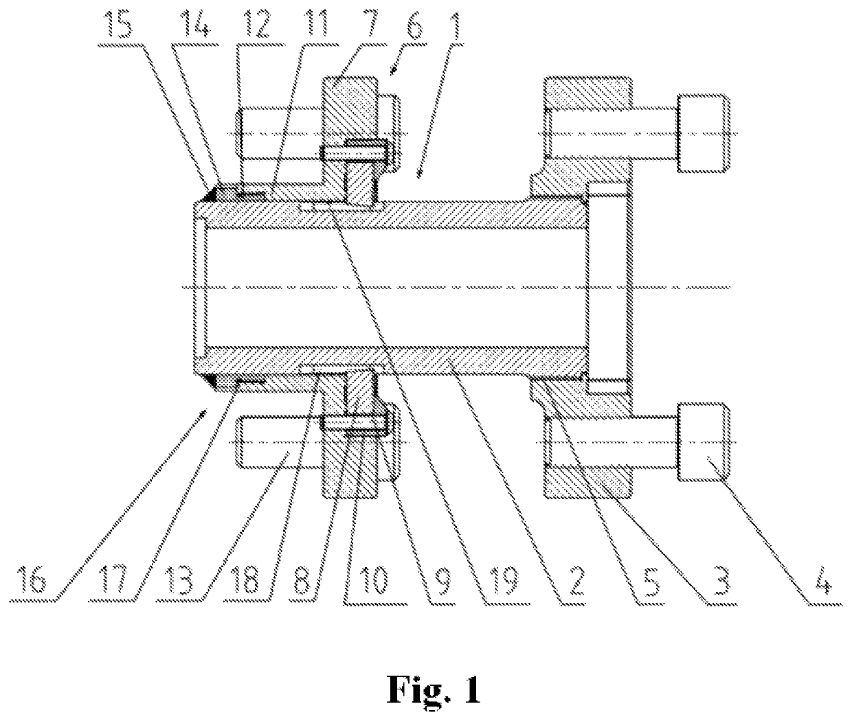
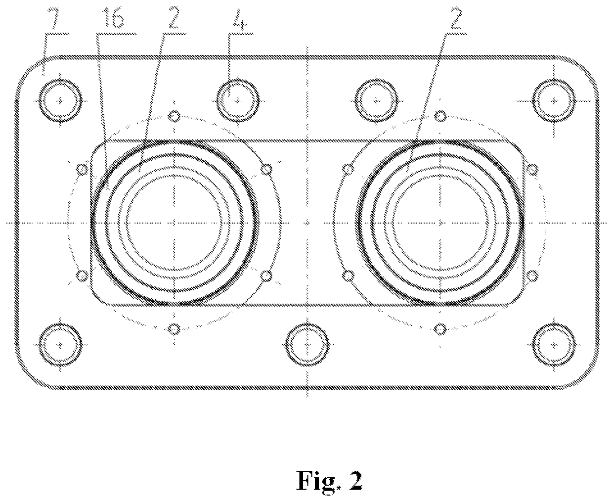
[0042]As presented in the embodiment in FIG. 1 and FIG. 2, the impact energy absorber for structural units connecting rail carriages according to the invention comprises an energy absorbing element 1 which is a set of two steel rods 2 made in the form of machinable sleeves or bars. At one end of each rod 2 there is fastened a mounting plate 3 with bolts 4 which connects the device of the invention with structural units connecting rail carriages. The connection between the mounting plate 3 and the rods 2 is a robust threaded connection 5 which is capable of transmitting both the tractive force and the impact force. This connection is to prevent the shift of the mounting plate 3 relative to the rod 2 at any load conditions. In the vicinity of the other end of each rod 2 there is a machining unit 6 comprising a tool mounting plate 7 with cutting tools 8 placed in the recesses and pressed by bolts 9 via pressure elements 10. The tool mounting plate 7 is fastened to the rods 2 via a slee...


PUM


Abstract

The device contains an energy absorbing element in a form of at least two parallel machinable rods placed at a distance from one another, and at least one thrust element used to transmit a tractive force between the machining unit and the rods. The device also features a tool mounting plate, forming a part of the machining unit, seated on the rods via guiding holes. A mounting plate is fastened on the rods and placed at a distance from the tool mounting plate.

Description

CROSS REFERENCE TO RELATED APPLICATIONS[0001]This application is a national stage application under 35 U.S.C. § 371 of International Application No. PCT / IB2016 / 051174, filed Mar. 2, 2016, which claims priority of Polish Patent Application No. P.411483, filed Mar. 5, 2015, the entire contents of each application being herein incorporated by reference.TECHNICAL FIELD[0002]The present invention refers to a device which absorbs impact energy in structural units connecting rail vehicles.BACKGROUND[0003]Patent specification PL202114 presents an impact energy absorber consisting of a rod which can be machined by cutting tools surrounding it, placed evenly in a body sleeve. In order to ensure the correct guiding of the cutting tools, their blades are placed in guides shaped on the outer surface of the rod.[0004]Patent specification PL211405 also presents an impact energy absorber consisting of a rod of a fluently changing diameter, which can be machined by cutting tools. In particular, this...

Claims


Application Information

Patent Timeline
Patent Type & Authority Patents(United States)
IPC IPC(8): B61G11/16
CPCB61G11/16F16B5/02F16B5/08
Inventor KUKULSKI, JANWASILEWSKI, LESZEK
Owner AXTONE SPOLKA AKCYJNA
Why Eureka
Try Eureka