
Method and apparatus for the recovery of drilling fluid from shaker tailings during active drilling

a technology of active drilling and drilling fluid, which is applied in the separation process, centrifugal force sediment separation, and the direction of borehole/well accessories, etc., can solve the problems of increased transportation and processing costs, hazardous to workers, and additional added costs from the need to add new drilling fluid

Active Publication Date: 2020-07-07
NAT OILWELL VARCO LP
View PDF4 Cites 1 Cited by
  • Summary
  • Abstract
  • Description
  • Claims
  • Application Information

AI Technical Summary

Problems solved by technology

But in either case, it is highly desirable to recover and reuse as much of the drilling fluid as possible because it is expensive.
Although these tailings may be discarded, they can contain substantial amounts of the oil or water-based drilling fluid.
In some instances, these cuttings have been collected and mixed with a stabilizing product and shipped to a processing facility for oil or water residue removal, however, this adds significant cost due to the transport and processing.
Additional added costs arise from the need to add new drilling fluid or fluid constituents in order to recover for the lost volume of drilling fluid.
Some such systems employ an initial washing technique using chemicals that are potentially hazardous to workers.
While theoretically producing cleaner solids, the technique results in the secondary problem of producing large volumes of oil-contaminated wash water for disposal.
These systems, however, have large footprints and necessitate added set up, maintenance and safety procedures.
Further, the mechanical forces these systems employ degrade (make smaller) the drilled solids, and then returns them to the active drilling fluid.
The smaller particles, called low gravity solids or ultra-fines, can lower drilling rates, yet they cannot be removed by the usual solids control equipment present at the rig.
The needed blending and fluid maintenance can substantially increase cost.
Such systems have suffered the disadvantages of high mechanical wear, corrosion, and have also had a high energy demand due, in large part, to the necessity of evaporating all water associated with the cuttings.
Further, these systems are generally set up away from the drilling site, thereby adding transportation cost and creating the possibility of spills.

Method used


Image

  • Method and apparatus for the recovery of drilling fluid from shaker tailings during active drilling
  • Method and apparatus for the recovery of drilling fluid from shaker tailings during active drilling
  • Method and apparatus for the recovery of drilling fluid from shaker tailings during active drilling

Examples


Embodiment Construction

[0039]This disclosure is directed to and describes various exemplary embodiments. The discussion of any embodiment is meant only to be exemplary of that embodiment, and is not intended to intimate that the scope of this disclosure, including the claims, is limited to that embodiment. The drawing figures are not necessarily to scale. Certain depicted features and components may be shown exaggerated in scale or in somewhat schematic form, and some details of conventional elements may not be shown in interest of clarity and conciseness.

[0040]In the following discussion and in the claims, the terms “including” and “comprising” are used in an open-ended fashion, and thus are to be interpreted to mean “including, but not limited to . . . .” Also, the term “couple” or “couples” is intended to mean either an indirect or direct connection. Thus, if a first device couples to a second device, the connection between the two devices may be through a direct connection between the two devices, or ...


PUM

PropertyMeasurementUnit
degree of rotationaaaaaaaaaa
angleaaaaaaaaaa

Abstract

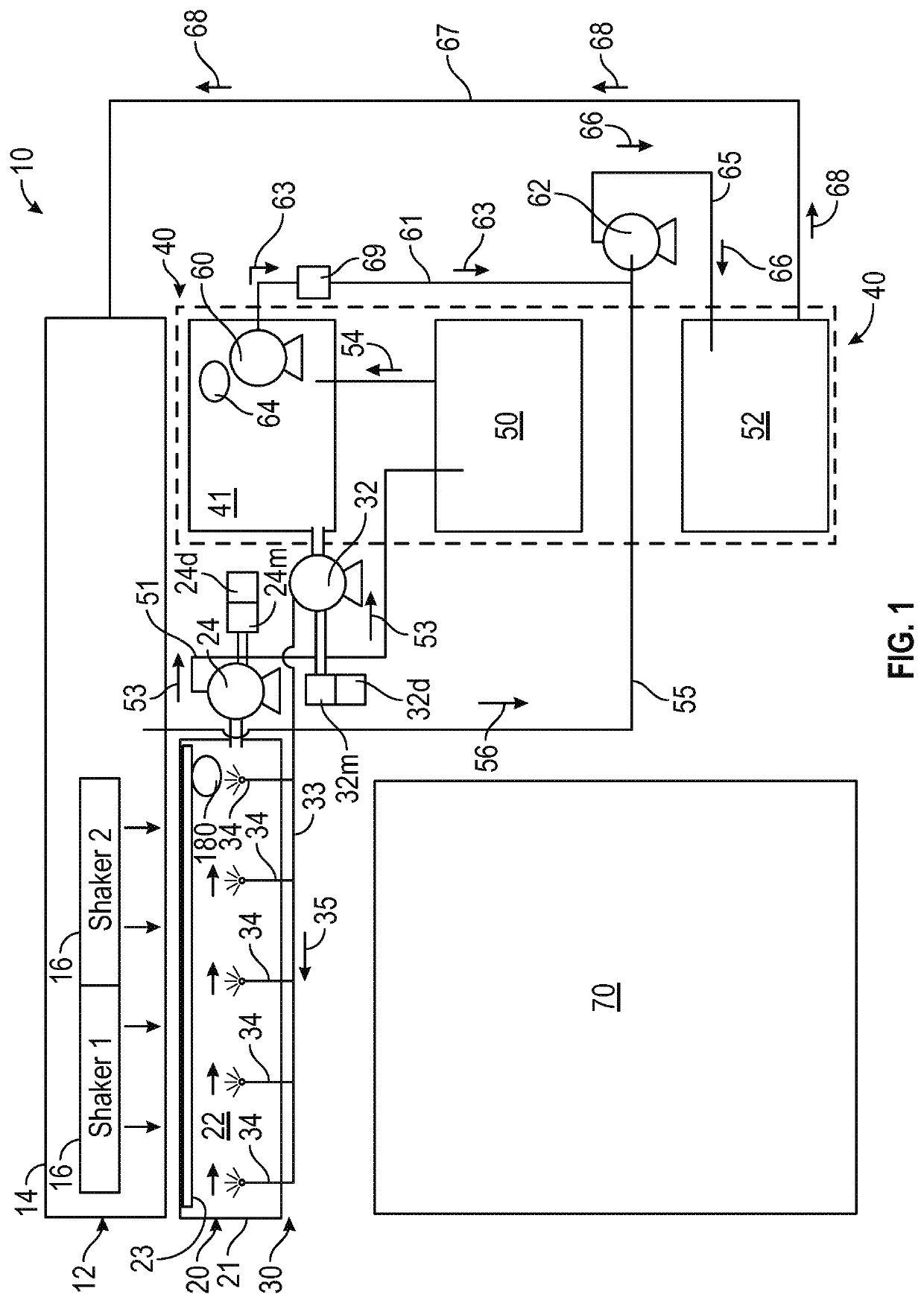
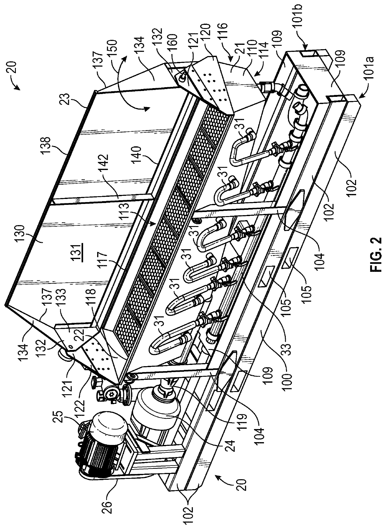
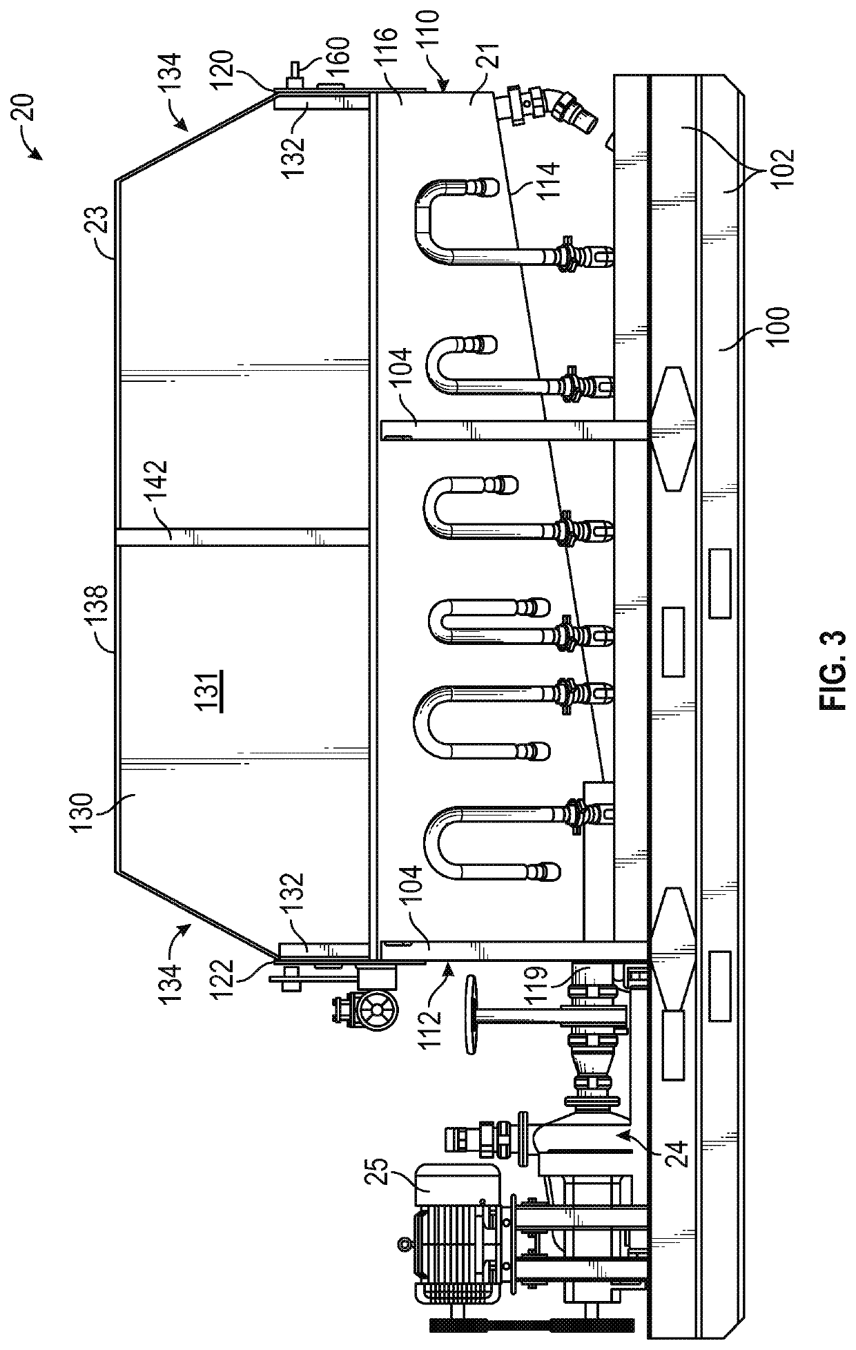
A system and method for recovering drilling fluid from shaker tailings includes a hopper and a cover that is pivotable between a first position in which the hopper is uncovered and a second position in which the hopper is covered. In the first position, the hopper receives the tailings, which are pumped via a low shear pump to a centrifuge. The drilling fluid extracted in the centrifuge is stored in a holding tank. In the second position, the cover is angled with respect to the direction of gravity so as to divert shaker tailings from being received in the hopper. Some fluid from the holding tank is sprayed into the hopper through nozzles to convey the deposited tailings toward the pump. A level detector senses the level of the mixture in the hopper, and an associated control system controls the pump speed and the cover position to control the operation.

Description

CROSS-REFERENCE TO RELATED APPLICATIONS[0001]Not applicable.STATEMENT REGARDING FEDERALLY SPONSORED RESEARCH OR DEVELOPMENT[0002]Not applicable.BACKGROUNDTechnical Field[0003]This disclosure relates generally to apparatus used in solids separation techniques, and in particular, in the separation of drill cuttings from drilling fluid. More particularly, it relates to methods and apparatus for the recovery of valuable drilling fluid from the tailings that come off of conventional shaker machines which make a first separation of drilling fluid from drill cuttings at the drilling site.General Background[0004]For the ultimate recovery of oil and gas, boreholes are typically drilled by rotating a drill bit that is attached to the bottom of a drill string. With weight applied to the drill string, the rotating drill bit engages the earthen formation and proceeds to form a borehole toward a target zone. This produces large quantities of rock particles, typically referred to as “drill cutting...

Claims


Application Information

Patent Timeline
Patent Type & Authority Patents(United States)
IPC IPC(8): B01D21/26E21B21/06E21B21/01B01D21/34
CPCB01D21/34E21B21/01E21B21/065B01D21/262
Inventor ZAZULA, RENNIE K.BIRD, DEAN M.OLSON, MIKE R.MACKLEY, NIEL P.
Owner NAT OILWELL VARCO LP
Learn More