Method of manufacturing prefilled drug delivery devices

a technology of drug delivery device and manufacturing method, which is applied in the direction of intravenous device, metal-working device, other medical device, etc., can solve the problems of drug waste, reduced assembly process flexibility, and a large-scale manufacturing of such prefilled drug delivery device more vulnerable to tolerance chains, so as to eliminate or reduce at least one drawback

Active Publication Date: 2020-06-30
NOVO NORDISK AS
View PDF16 Cites 0 Cited by
  • Summary
  • Abstract
  • Description
  • Claims
  • Application Information

AI Technical Summary

Benefits of technology

[0008]It is an object of the invention to eliminate or reduce at least one drawback of the prior art, or to provide a useful alternative to prior art solutions.
[0010]It is a further object of the invention to provide such a method which is simple to execute and which can be applied without major alterations to a conventional manufacturing setup.

Problems solved by technology

So, not only is initial priming of a prefilled drug delivery device an additional activity which is imposed on the user it also inevitably leads to some wastage of drug.
However, paradoxically, the requirement of preventing proximal piston rod movements reduces the flexibility in the assembly process, rendering a large scale manufacturing of such prefilled drug delivery devices more vulnerable to the tolerance chains.

Method used


Image

  • Method of manufacturing prefilled drug delivery devices
  • Method of manufacturing prefilled drug delivery devices

Examples


Embodiment Construction

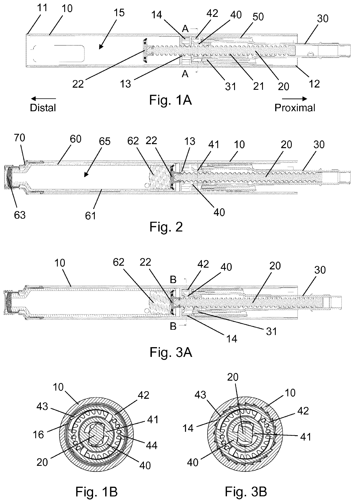
[0051]When in the following relative expressions, such as “clockwise” and “counter-clockwise”, are used, these refer to the appended figures and not necessarily to an actual situation of use. The shown figures are schematic representations for which reason the configuration of the different structures as well as their relative dimensions are intended to serve illustrative purposes only.

[0052]FIG. 1A is a longitudinal section view of a housing 10 for an injection pen, shown during assembly of the injection pen, and FIG. 1B is a cross-sectional view along line A-A of FIG. 1A. The housing 10 comprises a generally tubular wall extending between an open distal end 11 and an open proximal end 12, and an internal nut member 13 being fixed to an inside portion of the tubular wall in a central region between the distal end 11 and the proximal end 12. A piston rod 20 having a helical thread segment 21 and a non-circular cross-section extends through the nut member 13 and some distance into a ...


PUM


Abstract

The present invention provides a method of manufacturing a prefilled drug delivery device comprising the steps of arranging a piston rod member (20, 22, 120, 122) and a piston rod guide (40, 140) in a housing (10, 110) such that the piston rod member extends through a guide structure (13, 113) fixed in the housing and is surrounded by and operatively coupled with the piston rod guide, whereby rotation of the piston rod guide in a first direction relative to the housing causes distal movement of the piston rod member relative to the guide structure, and vice versa, and rotation of the piston rod guide in a second direction relative to the housing causes proximal movement of the piston rod member relative to the guide structure, and vice versa, and the piston rod guide is in a first state being capable of bi-directional rotation with respect to the housing, bringing a displaceable wall (62, 162) of a variable volume drug reservoir (60, 160) into abutment with a distal end portion of the piston rod member, moving the variable volume drug reservoir proximally relative to the housing to a completely mounted position, and shifting the piston rod guide irreversibly to a second state in which rotation of the piston rod guide in the second direction relative to the housing is prevented.

Description

CROSS-REFERENCE TO RELATED APPLICATIONS[0001]This application is a 35 U.S.C. § 371 National Stage application of International Application PCT / EP2016 / 075932 (published as WO 2017 / 072233), filed Oct. 27, 2016, which claims priority to European Patent Application 15192347.1, filed Oct. 30, 2015, the contents thereof which are incorporated by reference in their entirety.FIELD OF THE INVENTION[0002]The present invention relates to drug delivery devices suitable for self-administration by a user. More specifically the present invention relates to methods of manufacturing prefilled drug delivery devices.BACKGROUND OF THE INVENTION[0003]Today, many devices for self-administration of liquid drugs are based on technologies for percutaneous delivery, e.g. injection devices or infusion pumps, or for pulmonary delivery, e.g. inhalers. In the art of such drug delivery devices there is a marked distinction between a so-called prefilled device and a so-called reusable device. The term “reusable de...

Claims


Application Information

Patent Timeline
Patent Type & Authority Patents(United States)
IPC IPC(8): A61M5/315A61M5/31B21D53/00A61M5/20A61M5/24
CPCA61M5/31511B21D53/00A61M5/31513A61M5/3146A61M5/31515A61M2207/00A61M2005/2411A61M5/31501A61M5/31583A61M5/20
Inventor ANDERSEN, CARSTEN SCHAUROERVIG, SIMONHANSEN, STEFFEN
Owner NOVO NORDISK AS
Why Eureka
Try Eureka