Blowout preventer with pressure equalization block

a technology of blowout prevention and equalization block, which is applied in the direction of pressure relieving device on the sealing face, sealing/packing, and borehole/well accessories, etc. it can solve the problems of difficulty and cost of using the drilling rig in the completion process, inapplicability of the technology used for drilling to the completion/well servicing side of the industry, and personnel educated and trained for the drilling process are not always qualified for completion or well servicing work. achieve the effect of reducing the weight and

Active Publication Date: 2020-06-23
HORN EQUIP COMPANY
View PDF16 Cites 2 Cited by
  • Summary
  • Abstract
  • Description
  • Claims
  • Application Information

AI Technical Summary

Benefits of technology

[0014]The coiled tubing unit (CTU) of the invention utilizes a stadium style oval ram that increases the seal surface of the ram by 55% compared to a typical blowout preventer having a round ram. The CTU of the invention has a one piece design that will shear all sizes of coil tubing without changing blades or sealing packers. The shearing of larger sized tubing is limited by the force provided by the shear actuator being used. The CTU of the invention utilizes a shear booster actuator that doubles the force of the standard actuator, thereby insuring the ability to shear the largest size of tubing available. The CTU of the invention is designed so that doors on the BOP body can be removed from the body with little to no hydraulic oil spill and disassembled in an environmentally safe area. The CTU of the invention utilizes an equalization block system that is independent of the BOP body and can be easily replaced in the field such that no shop time is required.
[0031]The BOP of the invention uses a stadium / oval ram bore as opposed to circular design. Using this ram bore design provides flexibility in the design of the rams, as well as, providing for larger sealing surfaces on the rams.

Problems solved by technology

The size of a drilling rig and its components make it very difficult and costly to use the drilling rig in the completion process.
The personnel educated and trained for the drilling process are not always qualified for completion or well servicing work.
Therefore, technology used for drilling is not necessarily applicable to the completion / well servicing side of the industry.
Kicks can lead to a blowout, which is a potentially catastrophic event.

Method used


Image

  • Blowout preventer with pressure equalization block
  • Blowout preventer with pressure equalization block
  • Blowout preventer with pressure equalization block

Examples


Embodiment Construction

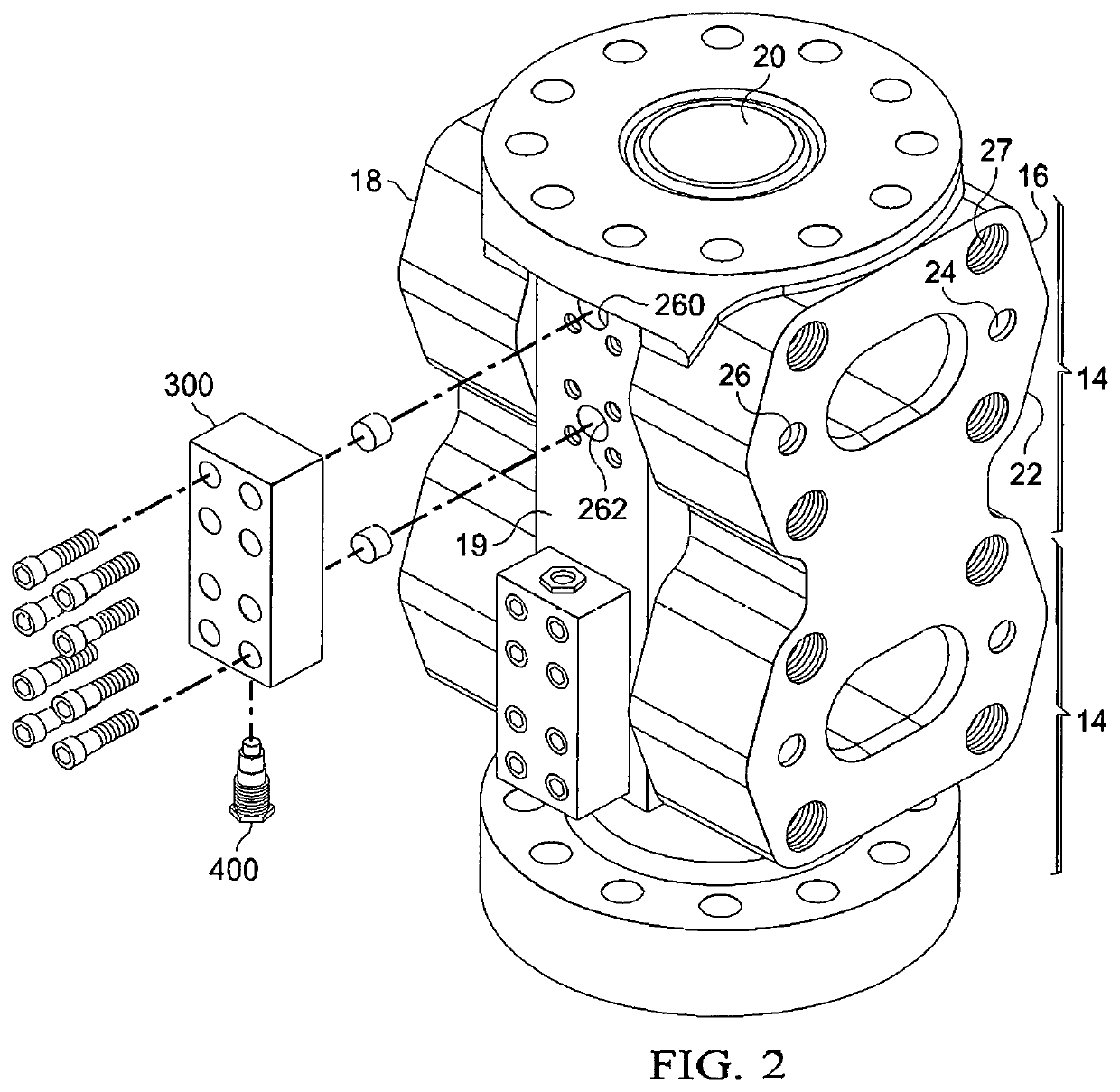
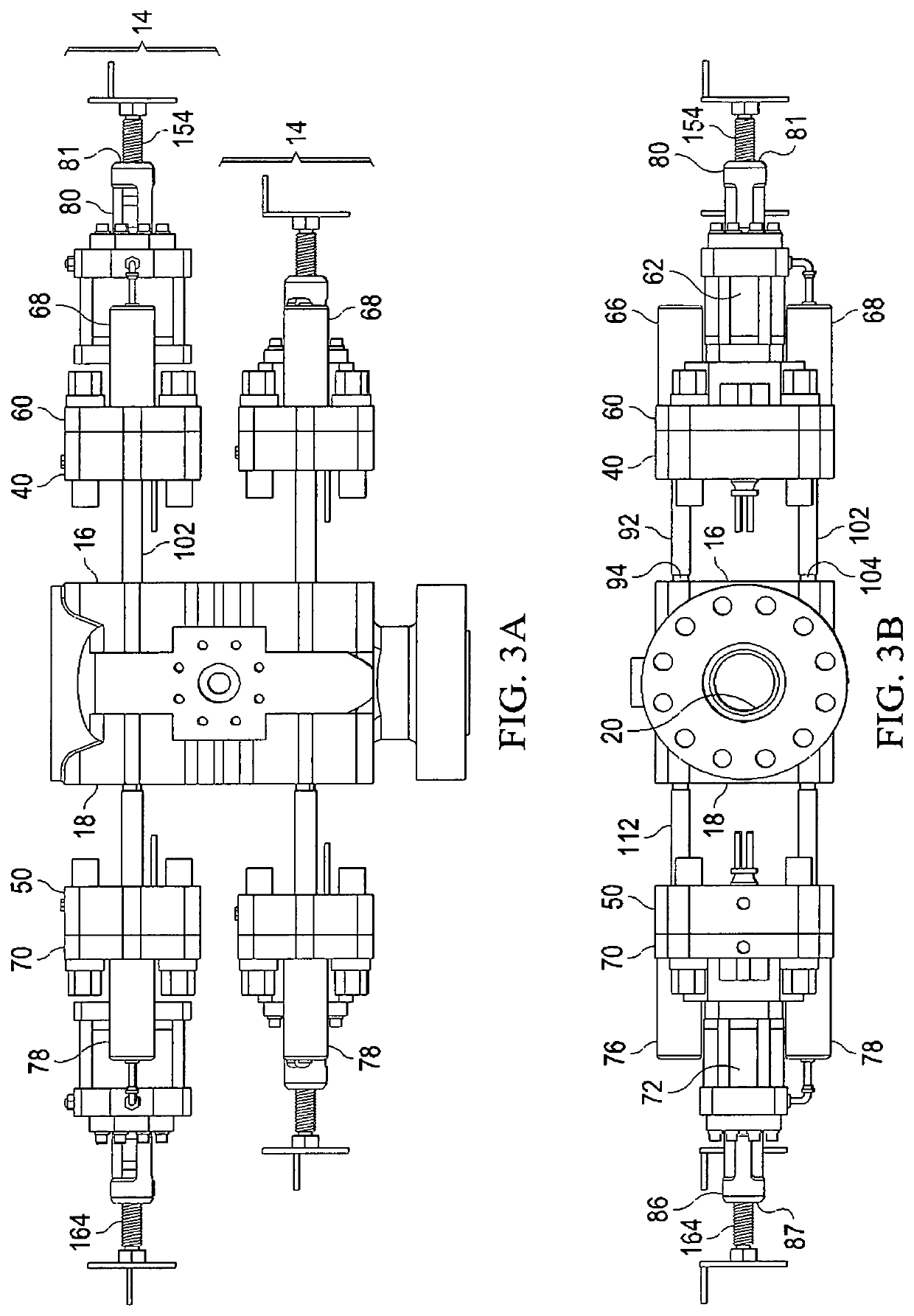
[0064]Referring now to FIG. 1, shown is blowout preventer assembly 10. Blowout preventer assembly 10 includes body 12. Body 12 is made up of a plurality of segments 14. Body 12 may be provided with two or more segments. For example, body 12 of FIG. 1 has four segments. Body 12 of FIG. 2 has two segments. Each of segments 14 have a first face 16 and a second face 18 (FIG. 2) on opposite sides of central section 19. Body 12 defines a vertical throughbore 20 (FIGS. 1, 2, 5) that passes between first face 16 and second face 18.

[0065]First face 16 defines first ram bore orifice 22, first open ram change rod orifice 24, and first closed ram change rod orifice 26 and a plurality of attachment bolt orifices 27 for receiving attachment bolts 29. Second face 18 defines second ram bore orifice 30 (not shown), second open ram change rod orifice 32 (not shown), and second closed ram change rod orifice 34 (not shown). Orifices 30, 32, and 43 of second face 18 are similarly configured to orifices ...


PUM


Abstract

A blowout preventer includes a body containing upper and lower ram assemblies. The body defines a surface pressure area above the upper rams and a wellbore pressure area between the upper and lower rams. An upper passageway communicates an outside of the body with the surface pressure area and a lower passageway communicates the outside with the wellbore pressure area. A valve adjacent the outside surface allows communication between the areas for pressure equalization. A bonnet is removed from the body by unfastening a flange from a face of the body and extending the flange from an assembled configuration to an extended configuration, thereby exposing a tool receiving surface on a ram change piston, wherein the piston communicates with the body and the flange. The tool surface is engaged for manipulating and disengaging the piston from one of the body and the flange, thereby facilitating removal of the flange.

Description

CROSS REFERENCE TO RELATED APPLICATIONS[0001]This application claims the priority of U.S. Provisional Patent Application No. 62 / 458,208 titled “BLOWOUT PREVENTER WITH PRESSURE EQUALIZATION BLOCK,” filed Feb. 13, 2017, the contents of which are hereby incorporated by reference.FIELD OF THE INVENTION[0002]The invention relates to blowout preventers. More particularly, the invention relates to pressure equalization methods and apparatus and to a method and apparatus to facilitate effectively servicing the blowout preventer.BACKGROUND OF THE INVENTION[0003]Coil tubing may be used in the completion and well servicing process of an oil and gas well. Coil tubing is cost effective for both processes. Coil tubing does everything wire line services do, plus adds the ability to control the movement of fluid or gas in and out of the well.[0004]The drilling process of the oil and gas well includes drilling a hole that typically ranges from 5½″ to 30″ into the earth to a desired depth. The hole i...

Claims


Application Information

Patent Timeline
Patent Type & Authority Patents(United States)
IPC IPC(8): E21B33/06E21B34/08F16K39/04
CPCE21B33/063E21B34/08E21B33/06F16K39/04E21B34/101
Inventor HORN, HOBY R.SPURLIN, SCOTT A.HAMBRIGHT, STEPHEN KOLBY
Owner HORN EQUIP COMPANY
Why Eureka
Try Eureka