Effective drainage method and system for flow division well

A discharge system and shunt well technology, applied in waterway systems, sewage discharge, drainage structures, etc., can solve the problems of electric shock hazard, easy leakage, difficult power supply, etc., and achieve no occupation of height space, strong anti-blocking ability, mature The effect of reliable prices

Pending Publication Date: 2019-02-19
WUHAN SHENGYU DRAINING SYST
View PDF9 Cites 1 Cited by
  • Summary
  • Abstract
  • Description
  • Claims
  • Application Information

AI Technical Summary

Problems solved by technology

However, in reality, electric control has the following problems: 1. Generally, flammable and explosive biogas will be produced in closed pipelines and sewage environments. General electric control devices are prone to explosion and unsafe. Therefore, when using electric control devices It is required that the electronic control part in contact with the biogas must have an explosion-proof function, so the price of the electronic control system is relatively expensive and the cost is high; 2. In the severe environment of stormy weather, power failure will occur, and the power will be diverted after power failure The equipment in the diversion well, abandonment well or interception well cannot work normally, resulting in urban waterlogging and other situations; 3. In rainy weather, the flooding of diversion wells, abandonment wells and interception wells ranges from several hours to several days In this way, the use of an electronic control device that is completely suitable for underwater use will be too redundant and cost too high, and the commonly used IP68-level electronic control device can be submerged within a few hours, and there are also situations where the capacity is insufficient; 4. The devices of the electric control system use unsafe voltage, and the high voltage is unsafe and prone to accidents; 5. After the electrical equipment is flooded, it is easy to leak electricity and there is a risk of electric shock; 6. When the electric control equipment (gates, weirs) are running It needs an upward or downward journey, which exposes the urban ground, which affects the urban landscape and traffic, and the excavation area is large during construction; 7. The electric control system uses 380V three-phase electricity, and the municipal power grid cannot supply power, so there is a problem of power supply difficulty question
[0004] In particular, for the occasions requiring concealed installation, and the power supply and costs of the electronic control system are not easy to solve
There are also certain problems in hydraulic control: the hydraulic station uses high-pressure oil pipes, and the cost of the hydraulic station and high-pressure oil pipes is relatively high; the rupture of high-pressure oil pipes will pollute the environment; after the electrical equipment is flooded, it is easy to leak electricity and there is a risk of electric shock; Gates, weir gates) require upward or downward strokes during operation, exposing the urban ground, affecting the urban landscape and traffic, and the excavation area is large during construction
[0005] In addition to the above-mentioned problems in the existing interception wells, diversion wells or abandonment wells, when urban waterlogging occurs, the channel to enter the natural water body or rainwater pipes will be quickly opened. At this time, there will be more dirty rainwater in the well. Will quickly pour into natural water bodies, causing serious environmental pollution

Method used


Image

  • Effective drainage method and system for flow division well
  • Effective drainage method and system for flow division well
  • Effective drainage method and system for flow division well

Examples


Embodiment 1

[0070] see image 3 As shown, the embodiment of the present invention provides an effective drainage method for the diversion well, as follows:

[0071] Set the first warning liquid level H0 in the well of the shunt well, and continuously collect the liquid level H in the shunt well, wherein,

[0072] On sunny days, the first pneumatic shut-off device is inflated, and the first water outlet pipe is closed;

[0073] After rainfall, when diverting dirty rainwater, H

[0074] When H≥H0, control the first pneumatic shut-off device to start deflation, and the opening of the first water outlet pipe gradually increases as time goes on;

[0075] Before the first water outlet pipe is fully opened, if the liquid level in the shunt well drops to H

[0076] When diverted clean rainwater enters the natural...

Embodiment 2

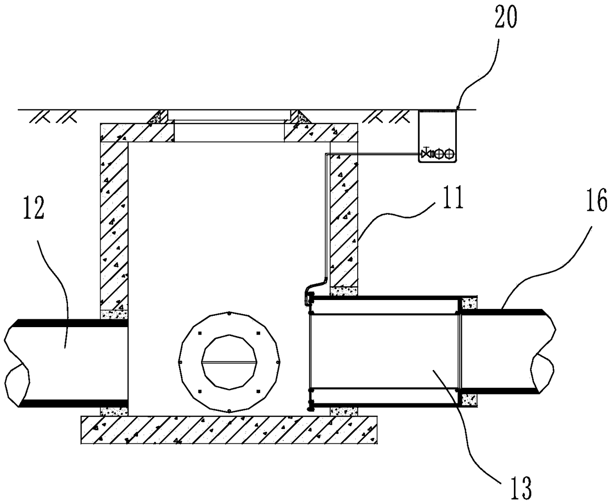
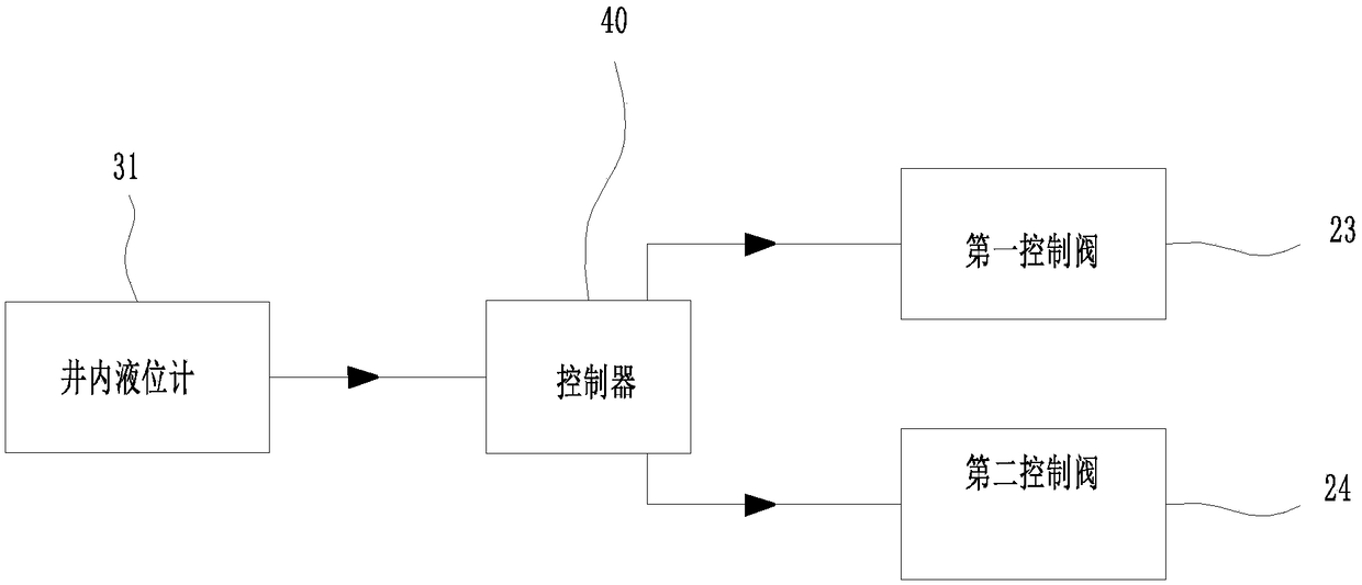
[0083] see figure 1 , figure 2 , image 3 , an effective drainage system for a diversion well, comprising: a compressed gas source, a gas delivery pipe, a control valve 20, a liquid level gauge 31 in the well and a pneumatic diversion well 10.

[0084] Wherein, the pneumatic diversion well 10 comprises a diversion well body 11 and a pneumatic shut-off device and a well liquid level gauge 31 arranged in the diversion well body 11,

[0085] The diversion well body is provided with a water inlet 12 and at least two water outlets, which are respectively the first water outlet and the second water outlet. The first water outlet is connected to the natural water body or rainwater pipe through the first outlet pipe 16, and the second water outlet is The second outlet pipe 17 is connected to the sewage pipe or the sewage treatment facility or the storage tank or the initial rain pipe or the sewage treatment facility, and at least two pneumatic intercepting devices are set on the fi...

Embodiment 3

[0099] see Figure 4 , Figure 5 and Figure 6 As shown, on the basis of embodiment 2, the body of the diversion well 10 in the present embodiment is provided with a water inlet 12, a first water outlet, a second water outlet and a third water outlet, and the first water outlet passes through the first water outlet. Outlet pipe 16 is connected to natural water body or rainwater pipe, and the second water outlet is connected to sewage pipe or sewage treatment facility or storage tank through second outlet pipe 17, and the third water outlet is connected to primary rain pipe or storage tank through the third outlet pipe 18 or Sewage treatment facilities, on the second outlet pipe 17 and the third outlet pipe 18, the pneumatic shut-off devices are respectively the second pneumatic shut-off device and the third pneumatic shut-off device, and each pneumatic shut-off device passes through a gas delivery sub-pipeline and gas delivery respectively. The main pipe is connected, and th...


PUM


Abstract

The invention discloses an effective drainage method for a flow division well. The method comprises the steps that a first alarm liquid level H0 in the flow division well is set, the liquid level H inthe flow division well is continuously collected, and on sunny days, a first pneumatic flow cutting device conducts air inflation, and a first water outlet pipe is closed; after rainy days, when dirty rainwater is divided, H is smaller than H0, the first water outlet pipe keeps closed, when H is larger than or equal to H0, the first pneumatic flow cutting device is controlled to start air discharging, and as time lapses, the aperture of the first water outlet pipe is gradually increased; before the first water outlet pipe is completely opened, if the liquid level in the flow division well descends until H is smaller than H0, the first pneumatic flow cutting device is controlled to stop air discharging, the first water outlet pipe keeps the current aperture, when the clean rainwater afterflow division enters natural water or a rainwater pipe, the first pneumatic flow cutting device conducts air discharging, and the first water outlet pipe is completely opened.

Description

technical field [0001] The invention relates to the drainage field, in particular to an effective drainage method and a drainage system for a diversion well. Background technique [0002] At present, in the diversion well, abandonment well and interception well system, the system is composed of water inlet pipe, outlet pipe and sewage intercepting pipe, which divert the domestic sewage or dirty rainwater and later rainwater in the drainage pipe, among which domestic sewage Or the dirty rainwater is intercepted to the sewage pipe and then transported to the sewage treatment plant for treatment and discharged after reaching the standard (further, the dirty rainwater can be stored or intercepted to the sewage treatment plant for treatment and discharged after reaching the standard), and the clean rainwater is directly discharged to the natural environment. in a body of water. [0003] The devices for diverting or intercepting flow all use gates or weir gates to switch the corr...

Claims


Application Information

Patent Timeline
Patent Type & Authority Applications(China)
IPC IPC(8): E03F1/00E03F5/10
CPCE03F1/00E03F5/10E03F5/101E03F5/105E03F5/107E03F2201/00
Inventor 李习洪周超
Owner WUHAN SHENGYU DRAINING SYST
Why Eureka
Try Eureka